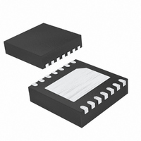
DS1842N+T&R Maxim Integrated Products, DS1842N+T&R Datasheet - Page 4

DS1842N+T&R
Manufacturer Part Number
DS1842N+T&R
Description
IC CURRENT MONITOR 14TDFN
Manufacturer
Maxim Integrated Products
Datasheet
1.DS1842NTR.pdf
(7 pages)
Specifications of DS1842N+T&R
Function
Current Monitor
Operating Temperature
-40°C ~ 85°C
Mounting Type
Surface Mount
Package / Case
14-TDFN Exposed Pad
Lead Free Status / RoHS Status
Lead free / RoHS Compliant
Current - Output
-
Voltage - Input
-
Accuracy
-
Sensing Method
-
Lead Free Status / Rohs Status
Lead free / RoHS Compliant
76V, APD, Bias Output Stage with
Current Monitoring
(T
4
9–12
PIN
A
13
14
—
4,
1
2
3
5
6
7
8
= +25°C, unless otherwise noted.)
_______________________________________________________________________________________
MIROUT
CLAMP
NAME
MIRIN
GATE
MIR1
MIR2
GND
N.C.
N.C.
LX
EP
Current Mirror Monitor Output, 10:1 Ratio
Current Mirror Monitor Output, 5:1 Ratio
No Connection. Can be connected to
GND for compatibility with the DS1842A.
No Connection. Not internally
connected.
Clamp Input. Disables the current mirror
output (MIROUT).
FET Gate Connection
Ground
FET Drain Connection. Connect to
switching inductor.
Current Mirror Input
Current Mirror Output. Connect to APD
bias pin.
Exposed Pad. Connect to ground.
7
6
5
4
3
FET ON-RESISTANCE vs. DRAIN CURRENT
1
V
GS
= 5V
10
V
Pin Description
GS
FUNCTION
V
GS
I
= 2.5V
DS
= 3.0V
V
GS
(mA)
= 3.6V
100
V
GS
Typical Operating Characteristics (continued)
= 10V
1000
CLAMP
GATE
700
600
500
400
300
200
100
GND
LX
0
FET DRAIN CURRENT vs. DRAIN VOLTAGE
0
V
GS
1
= 3.6V
DRAIN VOLTAGE (V)
DS1842
V
V
GS
GS
= 5V
= 10V
CURRENT
MIROUT
2
LIMIT
CURRENT MIRROR
V
GS
= 2.5V
V
Block Diagram
GS
3
SHUTDOWN
= 3.0V
THERMAL
4
MIRIN
MIR1
MIR2


