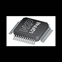
MPT612 NXP Semiconductors, MPT612 Datasheet - Page 17

MPT612
Manufacturer Part Number
MPT612
Description
The MPT612, the first dedicated IC for performing the Maximum Power Point Tracking (MPPT) function, is designed for use in applications that use solar photovoltaic (PV) cells or in fuel cells
Manufacturer
NXP Semiconductors
Datasheet
1.MPT612.pdf
(37 pages)
Available stocks
Company
Part Number
Manufacturer
Quantity
Price
Company:
Part Number:
MPT612FBD48,151
Manufacturer:
ON
Quantity:
22 150
Company:
Part Number:
MPT612FBD48,151
Manufacturer:
NXP Semiconductors
Quantity:
10 000
NXP Semiconductors
MPT612
Product data sheet
CAUTION
7.17.4 Code security (Code Read Protection)
7.17.5 External interrupt inputs
7.17.6 Memory mapping control
7.17.7 Power control
The MPT612’s Code Read Protection (CRP) feature allows users to restrict access to the
on-board flash, JTAG and ISP using different levels of security. When needed, CRP is
activated by programming a specific pattern into a dedicated flash location. IAP
commands are not affected by the CRP.
Three levels of the CRP are implemented in boot loader code:
The MPT612 includes up to three edge or level sensitive external interrupt inputs as
selectable pin functions. When the pins are combined, external events can be processed
as three independent interrupt signals. Optionally, the external interrupt inputs can be
used to wake-up the processor from Power-down mode and Deep power-down mode.
In additional, all 10 capture input pins can also be used as external interrupts without the
option to wake the device up from Power-down mode.
The memory mapping control changes the mapping of the interrupt vectors that appear
beginning at address 0x0000 0000. Vectors can be mapped to the bottom of the on-chip
flash memory or to the on-chip static RAM. This allows code running in different memory
spaces to have control of the interrupts.
The MPT612 supports three reduced power modes: Idle mode, Power-down mode and
Deep power-down mode.
In Idle mode, execution of instructions is suspended until a reset or interrupt is received.
Peripheral functions continue operation in Idle mode and can generate interrupts which
cause the processor to resume execution. Idle mode eliminates power used by the
processor itself, memory systems and related controllers and internal buses.
In Power-down mode, the oscillator is shut down and the chip receives no internal clock
signals. The processor state and registers, peripheral registers and internal SRAM
• CRP1: disables access to chip via the JTAG pins and allows partial flash updates
• CRP2: disables access to chip via the JTAG pins and only allows full flash erase and
• CRP3: Running an application with this level fully disables any access to chip via the
(excluding flash sector 0) using a limited set of the ISP commands. This mode is
useful when CRP is required and flash field updates are needed but all sectors
cannot be erased
update using a reduced set of the ISP commands
JTAG pins and the ISP. This mode effectively disables ISP override using PIO14 pin.
It is up to the user’s application to provide a flash update mechanism (if needed)
using IAP calls or call the re-invoke ISP command to enable flash update via pin
UART0.
If Code Read Protection level three (CRP3) is selected, no future factory testing
can be performed on the device.
All information provided in this document is subject to legal disclaimers.
Rev. 2 — 14 September 2010
Maximum power point tracking IC
© NXP B.V. 2010. All rights reserved.
MPT612
17 of 17


