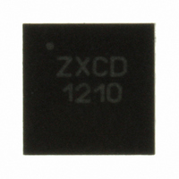
ZXCD1210JB16TA Diodes Zetex, ZXCD1210JB16TA Datasheet - Page 4

ZXCD1210JB16TA
Manufacturer Part Number
ZXCD1210JB16TA
Description
IC AMP AUDIO CLASS D 16QFN
Manufacturer
Diodes Zetex
Type
Modulatorr
Datasheet
1.ZXCD1210JB16TA.pdf
(8 pages)
Specifications of ZXCD1210JB16TA
Applications
Multimedia
Mounting Type
Surface Mount
Package / Case
16-QFN
Operational Class
Class-D
Audio Amplifier Output Configuration
1-Channel Mono
Audio Amplifier Function
Speaker
Total Harmonic Distortion
0.05%
Single Supply Voltage (typ)
16V
Dual Supply Voltage (typ)
Not RequiredV
Power Supply Requirement
Single
Power Dissipation
1W
Rail/rail I/o Type
No
Single Supply Voltage (min)
12V
Single Supply Voltage (max)
18V
Dual Supply Voltage (min)
Not RequiredV
Dual Supply Voltage (max)
Not RequiredV
Operating Temp Range
-40C to 70C
Operating Temperature Classification
Commercial
Mounting
Surface Mount
Pin Count
16
Package Type
QFN
Lead Free Status / RoHS Status
Lead free / RoHS Compliant
Other names
ZXCD1210JB16TR
Available stocks
Company
Part Number
Manufacturer
Quantity
Price
Company:
Part Number:
ZXCD1210JB16TA
Manufacturer:
ZETEX
Quantity:
1 000
Functional description
On chip series regulators drop the external V
supplies required by the internal circuitry of the device.
The on chip oscillator produces a clock which is set to approximately 200kHz by an external
capacitor and an on chip resistor. The clock is set at least an order higher in frequency than the
audio input. This clock is a triangle waveform which is used to modulate the incident analogue
signal in order to produce the required PWM output.
With no audio input signal applied, the PWM duty cycle is nominally 50%. As the audio input
signal ascends towards the peak level, the crossing points with the (higher frequency) triangle
wave also ascend. The PWM output exhibits a corresponding increase in output duty cycle.
Similarly, as the audio input signal descends, the duty cycle is correspondingly reduced. Thus the
triangle modulates the audio input generating a pulse width modulated (PWM) output. This
principle is illustrated below.
The PWM outputs drive the speaker load with the audio information contained in the PWM signal,
via the off chip gate drivers, H bridge and single stage LC filter network.
The triangle amplitude is approximately 1V. The audio inputs are internally biased to a DC voltage
of approximately V
triangular wave at the CK pin traverses between about 2.7V and 3.8V.
Issue 2 - October 2007
© Zetex Semiconductors plc 2007
CC
/5. The mid point DC level of the modulation control is around 2V. The
Triangle
Triangle
Output
Output
Audio
Audio
Triangle
Audio
Comparator O/P (duty cycle = 50%)
Comparator O/P (duty cycle = 75%)
Audio input
CC
PWM comparator
4
supply (12V recommended) to the 9V and 5.5V
PWM output
Triangle input
PWM output
ZXCD1210
www.zetex.com


