LM4927SD/NOPB National Semiconductor, LM4927SD/NOPB Datasheet - Page 12
LM4927SD/NOPB
Manufacturer Part Number
LM4927SD/NOPB
Description
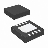
IC AMP AUDIO PWR 2.5W MONO 8LLP
Manufacturer
National Semiconductor
Series
Boomer®r
Type
Class ABr
Datasheet
1.LM4927SDNOPB.pdf
(14 pages)
Specifications of LM4927SD/NOPB
Output Type
1-Channel (Mono)
Max Output Power X Channels @ Load
2.5W x 1 @ 4 Ohm
Voltage - Supply
2.4 V ~ 5.5 V
Features
Depop, Differential Inputs, Shutdown, Thermal Protection
Mounting Type
Surface Mount
Package / Case
8-LLP
For Use With
LM4927SDBD - BOARD EVALUATION LM4927SD
Lead Free Status / RoHS Status
Lead free / RoHS Compliant
Other names
LM4927SD
LM4927SDNOPB
LM4927SDNOPBTR
LM4927SDNOPBTR
LM4927SDTR
LM4927SDNOPB
LM4927SDNOPBTR
LM4927SDNOPBTR
LM4927SDTR
Available stocks
Company
Part Number
Manufacturer
Quantity
Price
Company:

Part Number:
LM4927SD/NOPB
Manufacturer:
NS
Quantity:
9 435


www.national.com
Application Information
Since the same variations can have a significant effect on
PSRR and CMRR performance, it is highly recommended
that the input resistors be matched to 1% tolerance or better
for best performance.
AUDIO POWER AMPLIFIER DESIGN
Design a 1W/8Ω Audio Amplifier
A designer must first determine the minimum supply rail to
obtain the specified output power. The supply rail can easily
be found by extrapolating from the Output Power vs Supply
Voltage graphs in the Typical Performance Characteris-
tics section. A second way to determine the minimum supply
rail is to calculate the required V
add the dropout voltages. Using this method, the minimum
supply voltage is (Vopeak + (V
V
Given:
DO BOT
Tolerance
Power Output
Load Impedance
Input Level
Input Impedance
Bandwidth
20%
10%
5%
1%
0%
and V
DO TOP
0.95R
0.99R
0.8R
0.9R
R
R
i1
are extrapolated from the Dropout
1.05R
1.01R
1.2R
1.1R
R
R
i2
DO TOP
OPEAK
100Hz–20kHz
V
-0.500V
-0.250V
-0.125V
-0.025V
02
using Equation 7 and
+ (V
0
- V
(Continued)
01
DO BOT
31.25mA
15.63mA
3.125mA
±
62.5mA
I
)), where
LOAD
1Wrms
0.25dB
1Vrms
0
20kΩ
8Ω
12
Voltage vs Supply Voltage curve in the Typical Perfor-
mance Characteristics section.
Using the Output Power vs Supply Voltage graph for an 8Ω
load, the minimum supply rail just about 5V. Extra supply
voltage creates headroom that allows the LM4927 to repro-
duce peaks in excess of 1W without producing audible dis-
tortion. At this time, the designer must make sure that the
power supply choice along with the output impedance does
not violate the conditions explained in the Power Dissipa-
tion section. Once the power dissipation equations have
been addressed, the required differential gain can be deter-
mined from Equation 8.
From Equation 7, the minimum A
of 2.83 gives R
the bandwidth requirement which must be stated as a single
-3dB frequency point. Five times away from a -3dB point is
0.17dB down from passband response which is better than
the required
The high frequency pole is determined by the product of the
desired frequency pole, f
With a A
150kHz which is much smaller than the LM4927 GBWP of
10MHz. This figure displays that if a designer has a need to
design an amplifier with a higher differential gain, the
LM4927 can still be used without running into bandwidth
limitations.
VD
= 2.83 and f
±
0.25dB specified.
i
= 14kΩ. The final design step is to address
f
H
= 20kHz * 5 = 100kHz
R
H
f
H
/ R
= 100kHz, the resulting GBWP =
, and the differential gain, A
i
= A
VD
VD
is 2.83. A ratio of R
f
to R
VD
(7)
(8)
.
i
Related parts for LM4927SD/NOPB
Image
Part Number
Description
Manufacturer
Datasheet
Request
R

Part Number:
Description:
IC,Audio Amplifier,SINGLE,LLCC,8PIN,PLASTIC
Manufacturer:
National Semiconductor
Part Number:
Description:
National Semiconductor [8-Bit D/A Converter]
Manufacturer:
National Semiconductor
Datasheet:
Part Number:
Description:
National Semiconductor [Media Coprocessor]
Manufacturer:
National Semiconductor
Datasheet:
Part Number:
Description:
Digitally Controlled Tone and Volume Circuit with Stereo Audio Power Amplifier, Microphone Preamp Stage and National 3D Sound
Manufacturer:
National Semiconductor
Datasheet:
Part Number:
Description:
Digitally Controlled Tone and Volume Circuit with Stereo Audio Power Amplifier, Microphone Preamp Stage and National 3D Sound
Manufacturer:
National Semiconductor
Datasheet:
Part Number:
Description:
AC97 Rev 2 Codec with Sample Rate Conversion and National 3D Sound
Manufacturer:
National Semiconductor
Part Number:
Description:
Manufacturer:
National Semiconductor
Datasheet:
Part Number:
Description:
Manufacturer:
National Semiconductor
Datasheet:
Part Number:
Description:
General Purpose, Low Voltage, Low Power, Rail-to-Rail Output Operational Amplifiers
Manufacturer:
National Semiconductor
Datasheet:
Part Number:
Description:
8-bit 20 MSPS flash A/D converter.
Manufacturer:
National Semiconductor
Datasheet:
Part Number:
Description:
Low Noise Quad Operational Amplifier
Manufacturer:
National Semiconductor
Datasheet:
Part Number:
Description:
Quad Differential Line Receivers
Manufacturer:
National Semiconductor
Datasheet:
Part Number:
Description:
Quad High Speed Trapezoidal? Bus Transceiver
Manufacturer:
National Semiconductor
Datasheet:
Part Number:
Description:
Dual Line Receiver
Manufacturer:
National Semiconductor
Datasheet: