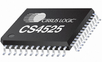
CS4525-CNZ Cirrus Logic Inc, CS4525-CNZ Datasheet - Page 49

CS4525-CNZ
Manufacturer Part Number
CS4525-CNZ
Description
IC AMP AUDIO PWR 30W QUAD 48QFN
Manufacturer
Cirrus Logic Inc
Series
Popguard®r
Type
Class Dr
Datasheet
1.CS4525-CNZ.pdf
(98 pages)
Specifications of CS4525-CNZ
Output Type
2-Channel (Stereo) or 4-Channel (Quad)
Package / Case
48-QFN
Max Output Power X Channels @ Load
30W x 1 @ 4 Ohm; 15W x 2 @ 8 Ohm
Voltage - Supply
8 V ~ 18 V
Features
ADC, Depop, I²C, I²S, Mute, PWM, Short-Circuit and Thermal Protection, Volume Control
Mounting Type
Surface Mount
Product
Class-D
Output Power
30 W
Thd Plus Noise
10 %
Operating Supply Voltage
2.5 V to 5 V
Supply Current
54 mA
Maximum Power Dissipation
180 mW
Maximum Operating Temperature
+ 70 C
Mounting Style
SMD/SMT
Audio - Load Impedance
4 Ohms, 6 Ohms, 8 Ohms
Audio Load Resistance
8 Ohms, 4 Ohms
Minimum Operating Temperature
0 C
Supply Voltage (max)
5.25 V
Supply Voltage (min)
2.375 V
Amplifier Class
D
No. Of Channels
4
Supply Voltage Range
8V To 18V
Load Impedance
4ohm
Operating Temperature Range
0°C To +70°C
Amplifier Case Style
QFN
No. Of Pins
48
Rohs Compliant
Yes
Lead Free Status / RoHS Status
Lead free / RoHS Compliant
For Use With
598-1586 - REFERENCE BOARD FOR CS4525 PWM
Lead Free Status / Rohs Status
Lead free / RoHS Compliant
Other names
598-1264
Available stocks
Company
Part Number
Manufacturer
Quantity
Price
Company:
Part Number:
CS4525-CNZ
Manufacturer:
CRYSTAL
Quantity:
329
Part Number:
CS4525-CNZ
Manufacturer:
TI/德州仪器
Quantity:
20 000
Part Number:
CS4525-CNZR
Manufacturer:
CIRRUSLOGICINC
Quantity:
20 000
DS726PP2
6.1.8.5
Four channel mapping output configurations are supported for the PWM_SIG output pins as shown in
Table 10
tions. When disabled, the PWM_SIG pins will continuously drive a logic ‘0’ if the HiZPSig bit is set and will
be held in a high-impedance state if the HiZPSig bit is clear. The configurations are selected by the PW-
MDSel[1:0] bits in the Output Cfg register. The PWM_SIG2 can be configured to output the sub channel
even if the Bass Manager is not enabled; however, its signal will be muted unless the Bass Manager is
enabled by the BassMgr[2:0] bits. It should be noted that the HiZPSig bit must be set to enable the
PWM_SIG output drivers.
To allow stereo headphone operation when the PWM logic-level outputs are mapped in a non-stereo out-
put configuration, if the HP_DETECT/MUTE pin is configured for headphone detection (the HP/Mute bit
is set), the PWM logic-level output mapping can be affected by the active state of the headphone detection
input signal. See the
tion.
It should be noted that signal on channels 1, 2, and the sub channel are dependent upon the digital sound
processing blocks being used. For instance, if the 2-way crossover is enabled, channel 1 and 2 contain
the 2-way crossover channel A high- and low-pass outputs respectively. For more information, see the
Digital Sound Processing
Referenced Control
PWMDSel[1:0].....................
HiZPSig ...............................
HP/Mute ..............................
BassMgr[2:0] .......................
PWMDSel[1:0]
below. The configurations support stereo, channel 1 with sub, and channel 2 with sub applica-
00
01
10
11
PWM_SIG Logic-Level Output Configurations
Headphone Detection & Hardware Mute Input
Register Location
“PWM Signals Output Data Select (PWMDSel[1:0])” on page 73
“Hi-Z PWM_SIG Outputs (HiZPSig)” on page 79
“HP_Detect/Mute Pin Mode (HP/Mute)” on page 70
“Bass Cross-Over Frequency (BassMgr[2:0])” on page 79
Table 10. PWM Logic-Level Output Configurations
section and
PWM_SIG1
Channel 1
Channel 1
Channel 2
Disabled.
Figure 14 on page
29.
section on
Sub Channel
Sub Channel
PWM_SIG2
page 51
Channel 2
Disabled.
for more informa-
CS4525
49


