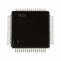
SC16C754BIBM,128 NXP Semiconductors, SC16C754BIBM,128 Datasheet - Page 28

SC16C754BIBM,128
Manufacturer Part Number
SC16C754BIBM,128
Description
IC UART QUAD 64BYTE 64LQFP
Manufacturer
NXP Semiconductors
Datasheet
1.SC16C754BIB80557.pdf
(51 pages)
Specifications of SC16C754BIBM,128
Number Of Channels
4, QUART
Fifo's
64 Byte
Voltage - Supply
2.5V, 3.3V, 5V
With Auto Flow Control
Yes
With False Start Bit Detection
Yes
With Modem Control
Yes
Mounting Type
Surface Mount
Package / Case
64-LQFP
Lead Free Status / RoHS Status
Lead free / RoHS Compliant
Other names
935279069128
SC16C754BIBM-F
SC16C754BIBM-F
SC16C754BIBM-F
SC16C754BIBM-F
Available stocks
Company
Part Number
Manufacturer
Quantity
Price
Company:
Part Number:
SC16C754BIBM,128
Manufacturer:
NXP Semiconductors
Quantity:
10 000
NXP Semiconductors
SC16C754B_4
Product data sheet
7.7 Modem Status Register (MSR)
This 8-bit register provides information about the current state of the control lines from the
modem, data set, or peripheral device to the processor. It also indicates when a control
input from the modem changes state.
per channel.
Table 15.
[1]
Bit
7
6
5
4
3
2
1
0
The primary inputs RI, CD, CTS, DSR are all active LOW, but their registered equivalents in the MSR and
MCR (in loopback) registers are active HIGH.
Symbol
MSR[7]
MSR[6]
MSR[5]
MSR[4]
MSR[3]
MSR[2]
MSR[1]
MSR[0]
Modem status register bits description
[1]
[1]
[1]
[1]
5 V, 3.3 V and 2.5 V quad UART, 5 Mbit/s (max.) with 64-byte FIFOs
Description
CD (active HIGH, logic 1). This bit is the complement of the CD input during
normal mode. During internal loopback mode, it is equivalent to MCR[3].
RI (active HIGH, logic 1). This bit is the complement of the RI input during
normal mode. During internal loopback mode, it is equivalent to MCR[2].
DSR (active HIGH, logic 1). This bit is the complement of the DSR input
during normal mode. During internal loopback mode, it is equivalent MCR[0].
CTS (active HIGH, logic 1). This bit is the complement of the CTS input
during normal mode. During internal loopback mode, it is equivalent to
MCR[1].
state. Cleared on a read.
from LOW to HIGH. Cleared on a read.
state. Cleared on a read.
state. Cleared on a read.
CD. Indicates that CD input (or MCR[3] in loopback mode) has changed
RI. Indicates that RI input (or MCR[2] in loopback mode) has changed state
DSR. Indicates that DSR input (or MCR[0] in loopback mode) has changed
CTS. Indicates that CTS input (or MCR[1] in loopback mode) has changed
Rev. 04 — 6 October 2008
Table 15
shows modem status register bit settings
SC16C754B
© NXP B.V. 2008. All rights reserved.
28 of 51


