PC6N139X Sharp Microelectronics, PC6N139X Datasheet
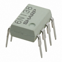
PHOTOCOUPLER GENERAL 8-DIP

PC6N139X

Manufacturer Part Number
PC6N139X
Description
PHOTOCOUPLER GENERAL 8-DIP
Manufacturer
Sharp Microelectronics
Datasheet

Specifications of PC6N139X

Rohs Status
RoHS non-compliant
Other names
425-1801-5
1. High current transfer ratio
2. High speed response
3. High common mode rejection voltage
4. TTL compatible output
5. Recognized by UL, file No. E64380
1. Interfaces for computer peripherals
2. Measuring instruments, Control equipment
3. Telephone sets
4. Signal transmission between circuits of
6N139
Notice
Internet Internet address for Electronic Components Group http://www.sharp.co.jp/ecg/
*1 50% duty cycle, Pulse width=1ms
*2 Pulse width 1 s, 300pulse/s
*3 Decreases at the rate of 0.7mA/˚C if the external temperature is 25˚C or more.
*4 40 to 60% RH, AC for 1 minute
*5 For 10 seconds
Output
Input
Applications
Absolute Maximum Ratings
different potentials and impedances
Features
( CTR : MIN. 500% at I
(
( CM
t
PHL
In the absence of confirmation by device specification sheets, SHARP takes no responsibility for any defects that may occur in equipment using any SHARP
devices shown in catalogs, data books, etc. Contact SHARP in order to obtain the latest device specification sheets before using any SHARP device.
H
1 : TYP. 0.22 s at R
: TYP. 500V/ s )
*1
*2
*3
*4
*5
Forward current
Peak forward current
Peak transient forward current
Reverse voltage
Power dissipation
Supply voltage
Output voltage
Emitter-base reverse
withstand voltage (Pin 5 to 7)
Average output current
Power dissipation
Isolation voltage
Operating temperature
Storage temperature
Soldering temperature
Parameter
F
=1.6mA )
L
=270 )
Symbol
V
V
V
T
iso
T
T
I
V
V
P
I
I
FM
I
EBO
P
opr
CC
O
stg
sol
F
F
O
(rms)
R
O
High Sensitivity, High Speed
*
* "OPIC" (Optical IC) is a trademark of the SHARP Corporation.
OPIC Photocoupler
An OPIC consists of a light-detecting element and signal-
processing circuit integrated onto a single chip.
Outline Dimensions
55 to 125
0.5 to 18
0.5 to 18
Rating
0 to 70
100
260
2.5
0.5
20
40
35
60
0.85
1
5
Primary side mark (Sunken place)
0.3
8
1
0.5
6N139
9.22
7
2
( Ta=25˚C )
0.1
1
2
3
4
Unit
0.5
NC
Anode
Cathode
NC
mW
mW
6
3
mA
mA
mA
kV
˚C
˚C
˚C
A
V
V
V
V
1.2
5
4
2.54
0.3
0.8
0.25
5
6
7
8
GND
V
V
V
CC
B
O
0.26
1
Internal connection
diagram
8
=0 to 13˚
7.62
0.1
7
2
0.3
( Unit : mm )
3
6
6N139
5
4

Related parts for PC6N139X

PC6N139X Summary of contents

Page 1

Features 1. High current transfer ratio ( CTR : MIN. 500 =1.6mA ) F 2. High speed response TYP. 0. =270 ) PHL L 3. High common mode rejection voltage ...

Page 2

Electro-optical Characteristics Parameter *6 Current transfer ratio Logic (0) output voltage Logic (1) output current Logic (0) supply current Logic (1) supply current Input forward voltage Input forward voltage temperature coefficient Input reverse voltage Input capacitance *8 Leak current (input-output) ...

Page 3

Test Circuit for Instantaneous Common Mode Rejection Voltage Fig. 1 Forward Current vs. Ambient Temperature ...

Page 4

Fig. 5 Current Transfer Ratio vs. Forward Current 1000 T =70˚C a 25˚C 0˚C 800 600 400 200 0 Forward current I (mA) F Fig. 7-a Propagation Delay Time vs. Ambient Temperature 2 t PLH 1 t PHL ...

Page 5

Test Circuit for Rise Time, Fall Time vs. Load Resistance Pulse generator Pulse input I duty ratio =1/ monitor 100 Precaution for use ( recommended that ...

Page 6

Application Circuits NOTICE The circuit application examples in this publication are provided to explain representative applications of SHARP devices and are not intended to guarantee any circuit design or license any intellectual property rights. SHARP takes no responsibility for any ...

Related keywords