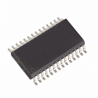
MAX3110ECWI+G36 Maxim Integrated Products, MAX3110ECWI+G36 Datasheet - Page 22

MAX3110ECWI+G36
Manufacturer Part Number
MAX3110ECWI+G36
Description
IC UART/TXRX RS232 W/CAPS 28SOIC
Manufacturer
Maxim Integrated Products
Type
SPI/MICROWIRE-Compatible UART with Integrated ESD-Protected RS-232 Transceiverr
Datasheet
1.MAX3110ECWIG36.pdf
(31 pages)
Specifications of MAX3110ECWI+G36
Features
Transceiver
Number Of Channels
1, UART
Protocol
RS232, RS485
Voltage - Supply
4.5 V ~ 5.5 V
With Irda Encoder/decoder
Yes
With False Start Bit Detection
Yes
With Cmos
Yes
Mounting Type
Surface Mount
Package / Case
28-SOIC (0.300", 7.50mm Width)
Data Rate
250 Kbps
Supply Voltage (max)
5.5 V
Supply Voltage (min)
4.5 V
Supply Current
0.6 mA
Maximum Operating Temperature
+ 70 C
Minimum Operating Temperature
0 C
Description/function
SPI/MICROWIRE-Compatible UART with integrated ESD-protected RS-232 transceiver
Mounting Style
SMD/SMT
Operating Supply Voltage
5 V
Propagation Delay Time Ns
150 ns
No. Of Channels
1
Uart Features
SPI/QSPI/MICROWIRE-Compatible µC Interface, Internal Charge-Pump Capacitors
Supply Voltage Range
4.5V To 5.5V
Rohs Compliant
Yes
Lead Free Status / RoHS Status
Lead free / RoHS Compliant
The transmitters are inverting-level translators that con-
vert CMOS-logic levels to ±5.0V EIA/TIA-232 levels. The
transmitters guarantee a 230kbps data rate with worst-
case loads of 3kΩ in parallel with 1000pF, providing
compatibility with PC-to-PC communication software
(such as LapLink™). Transmitters can be paralleled
because the outputs are forced into a high-impedance
state when the device is in hardware shutdown
(SHDN = GND). The MAX3110E/MAX3111E permit the
outputs to be driven up to ±12V while in shutdown.
The transmitter inputs do not have pull-up resistors.
Connect unused inputs to GND or V
The receivers convert RS-232 signals to CMOS-logic
output levels. The MAX3110E/MAX3111E receivers
have inverting outputs and are always active, even
when the part is in hardware (or software) shutdown.
Supply current falls to I
shutdown mode (SHDN = low). When shut down, the
device’s charge pumps are turned off, V+ is pulled
down to V
outputs are disabled (high impedance). The time
required to exit shutdown is typically 100µs, as shown
in Figure 7. Connect SHDN to V
mode is not used. The UART software shutdown does
not affect the RS-232 transceiver.
As with all Maxim devices, ESD-protection structures
are incorporated on all pins to protect against electro-
static discharges encountered during handling and
assembly. The driver outputs and receiver inputs of the
MAX3110E/MAX3111E have extra protection against
static electricity. Maxim’s engineers have developed
state-of-the-art structures to protect these pins against
ESD of ±15kV without damage. The ESD structures
withstand high ESD in all states: normal operation, shut-
down, and powered down. After an ESD event, the
MAX3110E/MAX3111E keep working without latchup,
whereas competing RS-232 products can latch and
must be powered down to remove latchup.
ESD protection is tested in various ways; the transmitter
outputs and receiver inputs devices are characterized
for protection to the following limits:
•
•
•
SPI/MICROWIRE-Compatible UART and ±15kV ESD-
Protected RS-232 Transceivers with Internal Capacitors
22
RS-232 Transceiver Hardware Shutdown
±15kV using the Human Body Model
±8kV using the Contact-Discharge Method specified
in IEC 1000-4-2
±15kV using the Air-Gap Method specified in IEC
1000-4-2
______________________________________________________________________________________
CC
, V- is pulled to ground, and the transmitter
CCSHDN(H)
±15kV ESD Protection
RS-232 Transmitters
RS-232 Receivers
CC
CC
when in hardware
.
if the shutdown
ESD performance depends on a variety of conditions.
Contact Maxim’s Quality Assurance (QA) group for a
reliability report that documents test setup, methodolo-
gy, and results.
Figure 8a shows the Human Body Model, and Figure
8b shows the current waveform it generates when dis-
charged into a low impedance. This model consists of a
100pF capacitor charged to the ESD voltage of inter-
est, which is then discharged into the test device
through a 1.5kΩ resistor.
The IEC 1000-4-2 standard covers ESD testing and
performance of finished equipment; it does not specifi-
cally refer to integrated circuits. The MAX3110E/
MAX3111E help you design equipment that meets
Level 4 (the highest level) of IEC 1000-4-2 without the
need for additional ESD-protection components.
The major difference between tests done using the
Human Body Model and IEC 1000-4-2 is higher peak
current in IEC 1000-4-2, because series resistance is
lower in the IEC 1000-4-2 model. Hence, the ESD that
withstands voltage measured to IEC 1000-4-2 is gener-
ally lower than that measured using the Human Body
Model. Figure 9a shows the IEC 1000-4-2 model, and
Figure 9b shows the current waveform for the ±8kV
IEC 1000-4-2 Level 4 ESD contact-discharge test.
Figure 7. MAX3111E Transmitter Outputs Exiting Shutdown or
Powering Up
5V/div
2V/div
0
0
V
CC
= 3.3V
LapLink is a trademark of Traveling Software.
40μs/div
ESD Test Conditions
Human Body Model
IEC 1000-4-2
T2OUT
SHDN
T1OUT


