SC28C94A1A,518 NXP Semiconductors, SC28C94A1A,518 Datasheet - Page 15
SC28C94A1A,518
Manufacturer Part Number
SC28C94A1A,518
Description
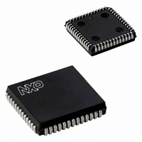
IC UART QUAD W/FIFO 52-PLCC
Manufacturer
NXP Semiconductors
Datasheet
1.SC28C94A1A518.pdf
(39 pages)
Specifications of SC28C94A1A,518
Features
False-start Bit Detection
Number Of Channels
4, QUART
Fifo's
8 Byte
Voltage - Supply
5V
With Auto Flow Control
Yes
With False Start Bit Detection
Yes
With Modem Control
Yes
With Cmos
Yes
Mounting Type
Surface Mount
Package / Case
52-PLCC
Lead Free Status / RoHS Status
Lead free / RoHS Compliant
Other names
568-1114-2
935262534518
SC28C94A1A-T
935262534518
SC28C94A1A-T
Available stocks
Company
Part Number
Manufacturer
Quantity
Price
Company:

Part Number:
SC28C94A1A,518
Manufacturer:
Maxim
Quantity:
21
Company:
Part Number:
SC28C94A1A,518
Manufacturer:
NXP Semiconductors
Quantity:
10 000


Philips Semiconductors
Mode Registers 0, 1 and 2
The addressing of the Mode Registers is controlled by the MR
Register pointer. On any access to the Mode Registers this pointer
is always incremented. Upon reaching a value of 2 it remains at 2
until changed by a CR command or a hardware reset.
MR0 – Mode Register 0
Mode Register 0 (MR0) is part of the UART configuration registers.
It controls the watch dog timer and the encoding of the number of
characters received in the RxFIFO. The lower four bits of this
register are not implemented in the hardware of the chip. MR0 is
normally set to either 80h or 00h. A read of this register will return
1111 (Fh) in the lower four bits.
The MR0 register is accessed by setting the MR Pointer to zero (0)
via the command register command 1011 (Bh).
MR0[7]: This bit enables or disables the RxFIFO watch dog timer.
MR0[7] = 1 enable watchdog timer
MR0[7] = 0 disable watchdog timer
MR0[6:4]: These bits are normally set to 0 except as noted in the
“Interrupt Threshold Calculation” description.
MR0[3:0]: These bits are not implemented in the chip. These bits
should be be considered “reserved.”
MR1 – Mode Register 1
MR1 is accessed when the MR pointer points to MR1. The pointer is
set to MR1 by RESET, a set pointer command applied via the CR or
after an access to MR0. After reading or writing MR1, the pointers
are set at MR2.
MR1[7] – Receiver Request-to-Send Flow Control
This bit controls the deactivation of the RTSN output (I/O2x) by the
receiver. This output is manually asserted and negated by
commands applied via the command register. MR1[7] = 1 causes
RTSN to be automatically negated upon receipt of a valid start bit if
the receiver FIFO is full. RTSN is re-asserted when an empty FIFO
position is available. This feature can be used to prevent overrun in
the receiver by using the RTSN output signal to control the CTS
input (the QUART I/O0 pin) of the transmitting device.
Use of this feature requires the I/O2 pin to be programmed as output
via the I/OPCR and to be driving a 0 via the OPR. When the RxFIFO
is full and the start bit of the ninth character is sensed the receiver
logic will drive the I/O2 pin high. This pin will return low when
another RxFIFO position is vacant.
MR1[6] – Receiver Interrupt Select 1
This bit is normally set to 0 except as noted in the “Interrupt
Threshold Calculation” description. MR1[6] operates with MR0[6] to
prevent the receiver from bidding until a particular fill level is
attained. For software compatibility this bit is designed to emulate
the RxFIFO interrupt function of previous Philips Semiconductors
UARTs.
MR1[5] – Error Mode Select
This bit selects the operating mode of the three FIFOed status bits
(received break, FE, PE). In the character mode, status is provided
on a character-by-character basis; the status applies only to the
character at the top of the FIFO.
In the block mode, the status provided in the SR for these bits is the
accumulation (logical-OR) of the status for all characters coming to
the top of the FIFO since the last reset error command was issued.
In the “Block Error” mode the ORing of the error status bits and the
presentation of them to the status register takes place as the bytes
enter the RxFIFO. This allows an indication of problem data when
2006 Aug 09
Quad universal asynchronous receiver/transmitter (QUART)
15
the error occurs after the leading bytes have been received. In the
character mode the error bits are presented to the status register
when the corresponding byte is at the top of the FIFO.
MR1[4:3] – Parity Mode Select
If “with parity” or “force parity” is selected, a parity bit is added to the
transmitted character and the receiver performs a parity check on
incoming data. MR1[4:3] = 11 selects the channel to operate in the
special wake-up mode (see ‘Wake-Up Mode’).
MR1[2] – Parity Type Select
This bit selects the parity type (odd or even) if the “with parity” mode
is programmed by MR1[4:3], and the polarity of the forced parity bit
if the “force parity” mode is programmed. It has no effect if the “no
parity” mode is programmed. In the special “wake-up” mode, it
selects the polarity of the transmitted A/D bit.
MR1[1:0] – Bits per Character Select
This field selects the number of data bits per character to be
transmitted and received. The character length does not include the
start, parity, and stop bits.
MR2 – Mode Register 2
MR2 is accessed when the channel MR pointer points to MR2,
which occurs after any access to MR1. Accesses to MR2 do not
change the pointer.
MR2[7:6] – Mode Select
The QUART can operate in one of four modes. MR2[7:6] = 00 is the
normal mode, with the transmitter and receiver operating
independently. MR2[7:6] = 01 places the channel in the automatic
echo mode, which automatically re-transmits the received data. The
following conditions are true while in automatic echo mode:
1. Received data is re-clocked and retransmitted on the TxD
2. The receive clock is used for the transmitter.
3. The receiver must be enabled, but the transmitter need not be
4. The TxRDY and TxEMT status bits are inactive.
5. The received parity is checked, but is not regenerated for
Two diagnostic modes can also be selected. MR2[7:6] = 10 selects
local loopback mode. In this mode:
1. The transmitter output is internally connected to the receiver
2. The transmit clock is used for the receiver.
3. The TxD output is held high.
4. The RxD input is ignored.
5. The transmitter must be enabled, but the receiver need not be
6. CPU to transmitter and receiver communications continue normally.
The second diagnostic mode is the remote loopback mode, selected
by MR2[7:6] = 11. In this mode:
1. Received data is re-clocked and retransmitted on the TxD output.
2. The receive clock is used for the transmitter.
3. Received data is not sent to the local CPU, and the error status
4. The received parity is not checked and is not regenerated for trans-
5. The receiver must be enabled, but the transmitter need not be enabled.
6. Character framing is not checked, and the stop bits are retrans-
7. A received break is echoed as received until the next valid start bit
output.
enabled.
transmission, i.e., transmitted parity bit is as received.
input.
enabled.
conditions are inactive.
mission, i.e., the transmitted parity bit is as received.
mitted as received.
is detected.
SC28C94
Product data sheet
Related parts for SC28C94A1A,518
Image
Part Number
Description
Manufacturer
Datasheet
Request
R

Part Number:
Description:
NXP Semiconductors designed the LPC2420/2460 microcontroller around a 16-bit/32-bitARM7TDMI-S CPU core with real-time debug interfaces that include both JTAG andembedded trace
Manufacturer:
NXP Semiconductors
Datasheet:

Part Number:
Description:
NXP Semiconductors designed the LPC2458 microcontroller around a 16-bit/32-bitARM7TDMI-S CPU core with real-time debug interfaces that include both JTAG andembedded trace
Manufacturer:
NXP Semiconductors
Datasheet:
Part Number:
Description:
NXP Semiconductors designed the LPC2468 microcontroller around a 16-bit/32-bitARM7TDMI-S CPU core with real-time debug interfaces that include both JTAG andembedded trace
Manufacturer:
NXP Semiconductors
Datasheet:
Part Number:
Description:
NXP Semiconductors designed the LPC2470 microcontroller, powered by theARM7TDMI-S core, to be a highly integrated microcontroller for a wide range ofapplications that require advanced communications and high quality graphic displays
Manufacturer:
NXP Semiconductors
Datasheet:
Part Number:
Description:
NXP Semiconductors designed the LPC2478 microcontroller, powered by theARM7TDMI-S core, to be a highly integrated microcontroller for a wide range ofapplications that require advanced communications and high quality graphic displays
Manufacturer:
NXP Semiconductors
Datasheet:
Part Number:
Description:
The Philips Semiconductors XA (eXtended Architecture) family of 16-bit single-chip microcontrollers is powerful enough to easily handle the requirements of high performance embedded applications, yet inexpensive enough to compete in the market for hi
Manufacturer:
NXP Semiconductors
Datasheet:
Part Number:
Description:
The XA-S3 device is a member of Philips Semiconductors? XA(eXtended Architecture) family of high performance 16-bitsingle-chip microcontrollers
Manufacturer:
NXP Semiconductors
Datasheet:

Part Number:
Description:
The NXP BlueStreak LH75401/LH75411 family consists of two low-cost 16/32-bit System-on-Chip (SoC) devices
Manufacturer:
NXP Semiconductors
Datasheet:
Part Number:
Description:
The NXP LPC3130/3131 combine an 180 MHz ARM926EJ-S CPU core, high-speed USB2
Manufacturer:
NXP Semiconductors
Datasheet:
Part Number:
Description:
The NXP LPC3141 combine a 270 MHz ARM926EJ-S CPU core, High-speed USB 2
Manufacturer:
NXP Semiconductors
Part Number:
Description:
The NXP LPC3143 combine a 270 MHz ARM926EJ-S CPU core, High-speed USB 2
Manufacturer:
NXP Semiconductors

Part Number:
Description:
The NXP LPC3152 combines an 180 MHz ARM926EJ-S CPU core, High-speed USB 2
Manufacturer:
NXP Semiconductors
Part Number:
Description:
The NXP LPC3154 combines an 180 MHz ARM926EJ-S CPU core, High-speed USB 2
Manufacturer:
NXP Semiconductors

Part Number:
Description:
Standard level N-channel enhancement mode Field-Effect Transistor (FET) in a plastic package using NXP High-Performance Automotive (HPA) TrenchMOS technology
Manufacturer:
NXP Semiconductors
Datasheet: