IS1U621L Sharp Microelectronics, IS1U621L Datasheet
IS1U621L
Specifications of IS1U621L


Related parts for IS1U621L


IS1U621L Summary of contents
Page 1
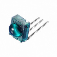
... Tolerance : ± 0.2 mm IS1U621L (Ta=25˚C) Rating Unit ˚ ˚C 260 ˚C 3.1mm * Tolerance : ± 0.2 mm Soldering area Recommended Unit operating conditions 4 IS1U621/IS1U621L 3.5 3.5 3.4 3.4 2.9 + 0.2 0.4 1.0 - 0.1 0.5 2.54 2. GND 3 V 3.5 3.5 3.4 3.4 2 ...
Page 2
... Output Internal Block Diagram Limiter Symbol Conditions I No input light, Output terminal OPEN CC V *3, Output terminal OPEN OH * < fo= 38kHz, Duty 50% B.P.F. Demodulator Integrator Comparator IS1U621/IS1U621L (Ta=25˚C, V =+5V) cc MIN. TYP. MAX. Unit - 2 0.45 0.6 V 400 - 800 s 400 - 800 kHz 8 ...
Page 3
... Fig. 2, the output signal shall meet the electrical characteristics in the attached list. =0˚ in the direction Y in Fig. 2, =0˚ in the direction X and <= 15˚ in the direction Y. 20cm 10k z Fig. 1 Transmitter SC External disturbing light detector face illuminance : Reception distance : L : Direction X : Direction Y Fig. 2 Standard optical system IS1U621/IS1U621L + 5V Vout Oscilloscope . Direction Y Direction X Vout ...
Page 4
... Fig. 4 Relative Reception Distance vs. Ambient 20˚ 30˚ 40˚ 50˚ 60˚ 70˚ 80˚ 90˚ (Conditions IS1U621/IS1U621L Characteristics (TYP.) for Reference - 20˚ - 10˚ 0˚ 10˚ Angular displacement Temperature (TYP.) for Reference 120 100 Unit SHARP standard transmitter Relative comparison with reception 20 distance at V =5V, =0˚ ...
Page 5
... Do not apply unnecessary force to the terminal. (6) Example of recommended external circuit (mount outer mounting parts near the sensor as much as possible IS1U621 GND Vout Connect capacitor C between Vout and GND terminals as shown above 2 1000 1100 IS1U621/IS1U621L Ve (Circuit constant ± GND 000pF 2 Vout ...
Page 6
Application Circuits NOTICE The circuit application examples in this publication are provided to explain representative applications of SHARP devices and are not intended to guarantee any circuit design or license any intellectual property rights. SHARP takes no responsibility for any ...