GP1UD262XK Sharp Microelectronics, GP1UD262XK Datasheet

RECEIVER REMOTE CTRL TOP 36.7KHZ

GP1UD262XK

Manufacturer Part Number
GP1UD262XK
Description
RECEIVER REMOTE CTRL TOP 36.7KHZ
Manufacturer
Sharp Microelectronics
Datasheet

Specifications of GP1UD262XK

Sensing Distance
5m
B.p.f. Center Frequency
36.7kHz
Voltage - Supply
2.7 V ~ 5.5 V
Current - Supply
200µA
Orientation
Top View
Mounting Type
Through Hole
Lead Free Status / Rohs Status
Contains lead / RoHS non-compliant
Other names
425-1117

Available stocks

Company
Part Number
Manufacturer
Quantity
Price
Part Number:
GP1UD262XK
Manufacturer:
SHARP
Quantity:
1 902
GP1UD26XK Series/GP1UD27XK Series
GP1UD28XK Series/GP1UD28YK Series
1. Low dissipation current:MAX.200 A (at V
2. Wide operating voltage range (2.7 to 5.5V)
3. Various attachment shape
GP1UD26XK Series
GP1UD28XK Series
2-0.75
R1.9
Notice
Internet Internet address for Electronic Components Group http://www.sharp.co.jp/ecg/
2-0.75
(1/12 of conventional type)
Outline Dimensions
Features
Unspecified tolerance: 0.3
2-0.5
2-0.5
*1
*1
0.6
0.6
2.54
2.54
In the absence of confirmation by device specification sheets, SHARP takes no responsibility for any defects that may occur in equipment using any SHARP
devices shown in catalogs, data books, etc. Contact SHARP in order to obtain the latest device specification sheets before using any SHARP device.
1
2
3
1
1 2 3
0.5
0.5
V
V
GND
7.3
7.3
2
OUT
CC
3
2.54
2.54
2-0.4
2-0.4
0.6
0.6
1
2
3
*1
*1
R1.9
V
V
GND
OUT
CC
Detector
center
1.6
1.6
Detector
center
Recommended drilling as viewed from the soldering face.
*1:The dimension of lead base
5.2
4
4
Marking
Marking
1.2
1.2
14.4
2.54
2.54
GP1UD26XK Series/GP1UD27XK Series/GP1UD28XK Series/GP1UD28YK Series
3.6
3.75 3.75
3.75 3.75
CC
(0.5)
(0.5)
3V)
2.54
2.54
3.6
1.2
1.2
GP1UD27XK Series
GP1UD28YK Series
R1.9
Energy Saving Type Low Dissipation
Current IR Detecting Unit for Remote
Control
1. Audio video equipment
2. Home appliances
Unspecified tolerance: 0.3
2-0.75
0.5
*1
0.6
Applications
2-0.5
*1
2.54
0.6
2.54
1
2
3
0.5
1
1
V
V
GND
7.3
0.5
2
OUT
CC
7.3
2 3
3
*1
2.54
2.54
R1.9
0.6
2-0.4
0.6
1
2
3
*1
V
V
GND
OUT
CC
1.6
Recommended drilling as viewed from the soldering face.
Detector
center
Recommended drilling as viewed from the soldering face.
1.6
*1:The dimension of lead base
1.6
0.4
3.7
4
10.4
2.54
Marking
4
5.4
1.2
2.54
3.75 3.75
1.2
Marking
3.75 3.75
6.8
3.6
1.4
(0.5)
2.54
1.2
1.4
2.54
1.2
(Unit : mm)

Related parts for GP1UD262XK

GP1UD262XK Summary of contents

Page 1

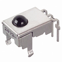
GP1UD26XK Series/GP1UD27XK Series/GP1UD28XK Series/GP1UD28YK Series GP1UD26XK Series/GP1UD27XK Series GP1UD28XK Series/GP1UD28YK Series Features 1. Low dissipation current:MAX.200 A (at V (1/12 of conventional type) 2. Wide operating voltage range (2.7 to 5.5V) 3. Various attachment shape Outline Dimensions GP1UD26XK Series 7.3 ...

Page 2

... Burst Wave f =*4 kHz Duty 50% O Transmitter signal 600 s 1 000 s Output signal Model Line-up B.P.F. center 40kHz GP1UD26XK GP1UD260XK 36kHz 38kHz GP1UD261XK GP1UD262XK 36.7kHz GP1UD263XK 32.75kHz GP1UD267XK 56.8kHz GP1UD26XK Series/GP1UD27XK Series/GP1UD28XK Series/GP1UD28YK Series ( Rating Unit 260 (5s) C Unit 2.7 to 5.5 V (Unless otherwise specified, condition shall be Ta=25˚ ...

Page 3

Fig.1 Internal Block Diagram AMP Performance Using the transmitter shown in Fig.2, the output signal of the light detecting unit is good enough to meet the following items in the standard optical system in Fig.3. 1. Linear reception distance characteristics ...

Page 4

Fig.3 Standard Optical System Transmitter Fig.4 B.P.F.Frequency Characteristics (TYP Carrier frequency (kHz) Fig.6 Sensitivity Angle (Vertical Direction) Characteristics (TYP.) (Reference) 15˚ 0˚ 100 30˚ 45˚ 40 60˚ 20 75˚ 90˚ GP1UD26XK Series/GP1UD27XK Series/GP1UD28XK Series/GP1UD28YK ...

Page 5

Fig.8 AEHA (Japan Association of Electrical Home Appliances) Code Pulse Width Characteristics (1st Bit) (TYP.) (Reference) (V 600 Low level pulse width 500 400 300 High level pulse width 200 Unit AEHA code generating transmitter 100 V 3V, Ta RT, ...

Page 6

Precautions for Operation 1. When this infrared remote control detecting unit shall be adopted for wireless remote control, please use it with the signal format of transmitter, which total duty ratio D (Pulse width of the presence of modulated IR) ...

Page 7

Application Circuits NOTICE The circuit application examples in this publication are provided to explain representative applications of SHARP devices and are not intended to guarantee any circuit design or license any intellectual property rights. SHARP takes no responsibility for any ...

Related keywords