DS25BR150TSD/NOPB National Semiconductor, DS25BR150TSD/NOPB Datasheet
DS25BR150TSD/NOPB
Specifications of DS25BR150TSD/NOPB
DS25BR150TSDTR
Available stocks


Related parts for DS25BR150TSD/NOPB

DS25BR150TSD/NOPB Summary of contents
Page 1
... Typical Application © 2007 National Semiconductor Corporation Features ■ 3.125 Gbps low jitter, high noise immunity, low power operation ■ ...
Page 2
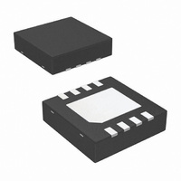
Block Diagram Pin Diagram Pin Descriptions Pin Name Pin Name NC 1 IN OUT- 6 OUT+ 7 VCC 8 GND DAP Ordering Codes and Configurations NSID DS25BR150TSD www.national.com 30005507 30005508 Pin Type Pin ...
Page 3
... Absolute Maximum Ratings If Military/Aerospace specified devices are required, please contact the National Semiconductor Sales Office/ Distributors for availability and specifications. Supply Voltage ( LVDS Input Voltage (IN+, IN−) LVDS Differential Input Voltage ((IN+) - (IN−)) LVDS Output Voltage (OUT+, OUT−) LVDS Differential Output Voltage ((OUT+) - (OUT−)) ...
Page 4
Symbol Parameter LVDS INPUT DC SPECIFICATIONS (IN+, IN-) V Input Differential Voltage ID V Differential Input High Threshold TH V Differential Input Low Threshold TL V Common Mode Voltage Range CMR I Input Current IN C Input Capacitance IN R ...
Page 5
AC Electrical Characteristics Over recommended operating supply and temperature ranges unless otherwise specified. (Notes 9, 10) Symbol Parameter LVDS OUTPUT AC SPECIFICATIONS (OUT+, OUT-) t Differential Propagation Delay High to Low PHLD t Differential Propagation Delay Low to High PLHD ...
Page 6
DC Test Circuits AC Test Circuits and Timing Diagrams www.national.com FIGURE 1. Differential Driver DC Test Circuit FIGURE 2. Differential Driver AC Test Circuit FIGURE 3. Propagation Delay Timing Diagram FIGURE 4. LVDS Output Transition Times 6 30005520 30005521 30005522 ...
Page 7
FIGURE 5. Jitter Measurements Test Circuit 7 30005529 www.national.com ...
Page 8
Device Operation INPUT INTERFACING The DS25BR150 accepts differential signals and allows simple coupling. With a wide common mode range, the DS25BR150 can be DC-coupled with all common differential drivers (i.e. LVPECL, LVDS, CML). The following three figures ...
Page 9
OUTPUT INTERFACING The DS25BR150 outputs signals are compliant to the LVDS standard. It can be DC-coupled to most common differential receivers. The following figure illustrates typical DC-coupled interface to common differential receivers and assumes that the receivers have high impedance ...
Page 10
Typical Performance A 2.5 Gbps NRZ PRBS-7 Output Eye Diagram V:100 mV / DIV, H: DIV Total Jitter as a Function of Input Amplitude www.national.com 30005531 A 3.125 Gbps NRZ PRBS-7 Output Eye Diagram V:100 mV / DIV, ...
Page 11
Physical Dimensions inches (millimeters) unless otherwise noted (See AN-1187 for PCB Design and Assembly Recommendations) Order Number DS25BR150TSD NS Package Number SDA08A 11 www.national.com ...
Page 12
... For more National Semiconductor product information and proven design tools, visit the following Web sites at: Products Amplifiers www.national.com/amplifiers Audio www.national.com/audio Clock Conditioners www.national.com/timing Data Converters www.national.com/adc Displays www.national.com/displays Ethernet www.national.com/ethernet Interface www.national.com/interface LVDS www.national.com/lvds Power Management www.national.com/power Switching Regulators www.national.com/switchers LDOs www ...