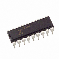
Z8622912PSC Zilog, Z8622912PSC Datasheet - Page 7

Z8622912PSC
Manufacturer Part Number
Z8622912PSC
Description
IC CCD W/2ND I2C ADD 18-DIP
Manufacturer
Zilog
Type
Video Decoderr
Datasheet
1.Z8622912PSC.pdf
(52 pages)
Specifications of Z8622912PSC
Applications
Set-Top Boxes, TV
Voltage - Supply, Digital
4.75 V ~ 5.25 V
Mounting Type
Through Hole
Package / Case
18-DIP (0.300", 7.62mm)
Processor Series
Z8622x
Core
Z80
Data Bus Width
8 bit
Program Memory Size
3.7 B
Maximum Clock Frequency
12 MHz
Number Of Programmable I/os
18
Operating Supply Voltage
4.75 V to 5.25 V
Maximum Operating Temperature
+ 70 C
Mounting Style
Through Hole
Minimum Operating Temperature
0 C
Lead Free Status / RoHS Status
Contains lead / RoHS non-compliant
Voltage - Supply, Analog
-
Lead Free Status / Rohs Status
No RoHS Version Available
Available stocks
Company
Part Number
Manufacturer
Quantity
Price
Part Number:
Z8622912PSC
Manufacturer:
ZILOG
Quantity:
20 000
ZiLOG
PIN DEFINITIONS
Inputs
I
reading when this input is Low(0). When the input is
High(1), the device selects 2Ah for writing and 2Bh for
reading.
SEN (Pin 4).
of operation on the Serial Control Port. When this pin is Low
(0), the SPI port is disabled and the SDO pin is in the high-
impedance state. Transitions on the SCK and SDA pins are
ignored. SPI mode operation is enabled when SMS is High
(1).
HIN (Pin 5).
at the CMOS level must be supplied. When the device is
used in VIDEO-LOCK mode, the signal pulls the on-chip
VCO within the proper range. The circuit uses the frequency
of this signal, which must be within +3% F
signal can be of either polarity. When used in the H-lock
mode, the VCO phase locks to the rising edge of this signal.
The HPOL bit of the H Position register can be set to operate
with either polarity of input signal. This signal is usually
the H Flyback signal. The timing difference between HIN
rising edge and the leading edge of composite sync (of VID-
EO input) is one of the factors which affects the horizontal
position of the display. Any shift resulting from the timing
of this signal can be compensated for with the horizontal
timing value in the H Position Register. H-lock is intended
for use when the part is generating an OSD display when
no video signal is present.
SMS (Pin 6).
rial Control Port. When this input is at a CMOS High state
(1), the Serial Control Port operates in the SPI mode. When
the input is Low (0), the Serial Control Port operates in the
I
(See Reset Operation section.)
VIDEO (Pin 7).
1.0V p-p (nom), band limited to 600 kHz. The circuit op-
erates with signal variation between 0.7–1.4V p-p. The po-
larity is sync tips negative. This signal pin should be AC
coupled through a 0.1 µF capacitor, driven by a source im-
pedance of 470 ohms or less.
SCK (Pin 15).
from the master control device. In I
clock rate is expected to be within I
the maximum clock frequency is 10 MHz.
2
2
C SEL (Pin 1).
C slave mode. In SPI mode, the SEN pin must be tied High.
For this pin, the Horizontal Sync input signal
This pin enables the signal for the SPI mode
This pin allows the mode select pin for the Se-
This pin is an input for a serial clock signal
This pin is a composite NTSC video input,
This pin selects 28h for writing and 29h for
2
2
C mode operation, the
C limits. In SPI mode,
h
, but the overall
Reset Operation.
the Low (0) state, the part is in the Reset state; therefore, in
the I
When SPI mode is used, if three wire operation is required,
both SMS and SEN can be tied together and used as the
NReset input. In either mode, NReset must be held Low (0)
for at least 100 ns.
Input/Output
V
of operation, the internal vertical sync circuits lock to the
V
rising or falling edge of the signal in accordance with the
setting of the V Polarity command. The default is rising
edge. The V
In INTRO Mode, when configured for internal vertical syn-
chronization, this pin is an output pin providing an interrupt
signal to the master control device in accordance with the
settings in the Interrupt Mask Register.
SDA (Pin 14).
I
line for sending and receiving serial data. In SPI mode op-
eration, the device operates as a serial data input. SPI mode
output data is available on the SDO pin.
Outputs
RED, GREEN, BLUE (Pins 2, 3, 18).
tive-acting CMOS-level signals.
•
•
Note:
CSync (Pin 8).
tied between this pin and analog ground V
pacitor stores the sync slice level voltage.
LPF (Pin 9).
be tied between this pin and analog ground V
must also be second capacitor from the pin to V
2
IN
C mode operation, this pin serves as the bidirectional data
IN
/INTRO (Pin 13).
Color Mode: Red, Green, and Blue characters are in-
corporated as video outputs for use in a color receiver
Mono Mode: In this mode, all three outputs carry the
character luminance information
2
input signal applied at this pin. The part locks to the
C mode, the SEN pin can be used as an NReset input.
The selection of Color/Mono Mode is user controlled in
bit D
Internal Registers section.)
1
of the Configuration Register (Address=00h). (See
IN
Loop Filter. A series RC low-pass filter must
When the Serial Control Port has been set to
pulse must be at least 2 lines wide.
Sync slice level. A 0.1 µF capacitor must be
When the SMS and SEN pins are both in
In external (EXT) vertical lock mode
These pins are osi-
SS
(A). This ca-
SS
(A). There
SS
(A).


