BU1425AKV Rohm Semiconductor, BU1425AKV Datasheet - Page 8
BU1425AKV
Manufacturer Part Number
BU1425AKV
Description
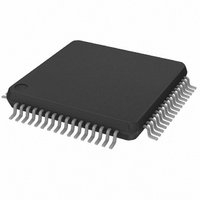
IC ENCODER NTSC/PAL DGTL VQFP64
Manufacturer
Rohm Semiconductor
Type
NTSC/PAL Encoderr
Datasheet
1.BU1425AK.pdf
(33 pages)
Specifications of BU1425AKV
Applications
Video
Voltage - Supply, Analog
4.5 V ~ 5.5 V
Voltage - Supply, Digital
4.5 V ~ 5.5 V
Mounting Type
Surface Mount
Package / Case
64-TQFP, 64-VQFP
Lead Free Status / RoHS Status
Lead free / RoHS Compliant
Available stocks
Company
Part Number
Manufacturer
Quantity
Price
Company:

Part Number:
BU1425AKV
Manufacturer:
Rohm Semiconductor
Quantity:
10 000


8
Multimedia ICs
Pin No.
28
27
29
32
33
34
35
37
Pin name
SLABEB
VREF-C
PIXCLK
ADDH
COUT
HSY
VSY
INT
I / O
I / O
I / O
O
O
I
I
I
I
Equivalent circuit
BU1425AK / BU1425AKV
This is the horizontal synchronization
signal pin. Negative polarity Hsync
signals are input (when SLABEB =
LOW) or output (when SLABEB =
HIGH) here. This is also used as the
synchronization signal for fixing the
PIXCLK output phase.
Vertical synchronization signals (Vsync)
are input (when SLABEB = LOW) or
output (when SLABEB = HIGH) here.
The internal processing clock is divid-
ed in half and output. Data is read at
the point at which the edge of this
clock changes. This can also be used
as the clock for the OSD IC.
This pin switches between interlace
(when HIGH) and non-interlace (when
LOW) modes. This pin is effective in
both the VIDEO-CD and CD-G
modes.
This pin switches between the Master
(when HIGH) and Slave (when LOW)
modes. It is effective in the non-
interlace mode, and it switches bet-
ween – 0.5 lines (when LOW) and + 0.5
lines (when HIGH) for the number of
lines in an interlace field.
This is the reference voltage generator
circuit monitoring pin which deter-
mines the output amplitude (output cur-
rent for 1 LSB) of the DAC. A 0.01 F
capacitor should be attached between
this and pin 43 (AV
This is the chrominance output pin for
the S pin.
Function
DD
).
Related parts for BU1425AKV
Image
Part Number
Description
Manufacturer
Datasheet
Request
R

Part Number:
Description:
Manufacturer:
Rohm Semiconductor
Datasheet:
Part Number:
Description:
Manufacturer:
Rohm Semiconductor
Datasheet:
Part Number:
Description:
Manufacturer:
Rohm Semiconductor
Datasheet:
Part Number:
Description:
Manufacturer:
Rohm Semiconductor
Datasheet:
Part Number:
Description:
Manufacturer:
Rohm Semiconductor
Datasheet:
Part Number:
Description:
Manufacturer:
Rohm Semiconductor
Datasheet:
Part Number:
Description:
Manufacturer:
Rohm Semiconductor
Datasheet:
Part Number:
Description:
Manufacturer:
Rohm Semiconductor
Datasheet:
Part Number:
Description:
Manufacturer:
Rohm Semiconductor
Datasheet:
Part Number:
Description:
Manufacturer:
Rohm Semiconductor
Datasheet:
Part Number:
Description:
Manufacturer:
Rohm Semiconductor
Datasheet:
Part Number:
Description:
Manufacturer:
Rohm Semiconductor
Datasheet:

Part Number:
Description:
DIODE SWITCH 80V 25MA SMD5 TR
Manufacturer:
Rohm Semiconductor
Datasheet: