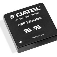
UWR-5/8-D24A Murata Power Solutions Inc, UWR-5/8-D24A Datasheet - Page 6

UWR-5/8-D24A
Manufacturer Part Number
UWR-5/8-D24A
Description
DC/DC Converters & Regulators 40W 24V to 5V 8A
Manufacturer
Murata Power Solutions Inc
Series
UWRr
Datasheet
1.UWR-57-D12A-C.pdf
(10 pages)
Specifications of UWR-5/8-D24A
Product
Isolated
Output Power
40 W
Input Voltage Range
18 V to 36 V
Input Voltage (nominal)
24 V
Number Of Outputs
1
Output Voltage (channel 1)
5 V
Output Current (channel 1)
8 A
Isolation Voltage
1.5 KV
Lead Free Status / Rohs Status
Lead free / RoHS Compliant
Available stocks
Company
Part Number
Manufacturer
Quantity
Price
Company:
Part Number:
UWR-5/8-D24A-C
Manufacturer:
TI
Quantity:
5
Trimming Output Voltage
to adjust the output voltages ±5%. Adjustments to the output voltages
can be accomplished via a trim pot (Figure 5) or a single fixed resistor as
shown in Figures 6 and 7. A single fixed resistor can increase or decrease
the output voltage depending on its connection. Resistors should be located
close to the converter and have TCR's less than 100ppm/°C to minimize
sensitivity to changes in temperature. If the trim function is not used, leave
the trim pin floating.
will decrease the output voltage. A resistor connected from the Trim (pin 8)
to the –Output (pin 7) , –Sense where applicable, will increase the output
voltage.
affect on the converter’s performance and are not recommended. Exces-
sive trim adjustment of the output voltage can cause the overvoltage pro-
tection circuitry to activate (see Performance Specifications for overvoltage
limits). Power derating is based on maximum output current and voltage
at the converter's output pins. Use of trim can cause output voltages to
increase thereby increasing output power beyond the UWR's specified
rating or cause output voltages to climb into the output overvoltage region.
Therefore:
Figure 6. Trim Connections To Decrease Output Voltages Using Fixed Resistors
UWR 26-40W converters have a trim capability (pin 8) that allows users
A single resistor connected from the Trim (pin 8) to the +Output (pin 6),
Trim adjustments greater than the specified ±5% can have an adverse
2
4
1
2
4
1
(V
OUT
–INPUT
ON/OFF
CONTROL
+INPUT
–INPUT
ON/OFF
CONTROL
+INPUT
at pins) x (I
Figure 5. Trim Connections Using A Trimpot
OUT
+OUTPUT
–OUTPUT
+OUTPUT
–OUTPUT
) <= rated output power
TRIM
TRIM
6
8
7
6
8
7
R
TRIM DOWN
www.murata-ps.com
TURNS
20k
5-22
Single Output, High-Density, 3.3V
LOAD
LOAD
Figure 7. Trim Connections To Increase Output Voltages Using Fixed Resistors
Soldering Guidelines
Murata Power Solutions recommends the specifications below when installing these
converters. These specifications vary depending on the solder type. Exceeding these
specifications may cause damage to the product. Be cautious when there is high
atmospheric humidity. We strongly recommend a mild pre-bake (100° C. for 30
minutes). Your production environment may differ; therefore please thoroughly review
these guidelines with your process engineers.
Note: Resistor values are in k
For Sn/Ag/Cu based solders:
Maximum Preheat Temperature
Maximum Pot Temperature
Maximum Solder Dwell Time
For Sn/Pb based solders:
Maximum Preheat Temperature
Maximum Pot Temperature
Maximum Solder Dwell Time
Wave Solder Operations for through-hole mounted products (THMT)
tolerances of resistors and factory-adjusted output accuracy.
2
4
1
–INPUT
ON/OFF
CONTROL
+INPUT
Technical enquiries email: sales@murata-ps.com, tel:
R
OUT
R
T
Trim Equations For 3.3 Volt Models
T
DOWN
Trim Equations For 5 Volt Models
DOWN
V
and 5 V
R
O
R
(k ) =
UWR 26-40W Series
T
(k ) =
= desired output voltage.
T
UP
UP
+OUTPUT
–OUTPUT
(k ) =
+SENSE
–SENSE
(k ) =
TRIM
OUT
2.49(V
2.49(V
Accuracy of adjustment is subject to the
5 – V
, 26-40 Watt, DC/DC Converters
3.3 – V
V
6
8
7
V
O
6.25
O
O
3.06
MDC_UWR26-40W_B05 Page 6 of 10
O
– 5
– 2.51)
O
– 3.3
R
115° C.
270° C.
7 seconds
105° C.
250° C.
6 seconds
– 1.23)
TRIM UP
O
–16.9
–13
–16.9
–13
LOAD
+1 508 339 3000


