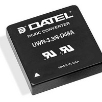
UWR-5/8-D24A Murata Power Solutions Inc, UWR-5/8-D24A Datasheet - Page 5

UWR-5/8-D24A
Manufacturer Part Number
UWR-5/8-D24A
Description
DC/DC Converters & Regulators 40W 24V to 5V 8A
Manufacturer
Murata Power Solutions Inc
Series
UWRr
Datasheet
1.UWR-57-D12A-C.pdf
(10 pages)
Specifications of UWR-5/8-D24A
Product
Isolated
Output Power
40 W
Input Voltage Range
18 V to 36 V
Input Voltage (nominal)
24 V
Number Of Outputs
1
Output Voltage (channel 1)
5 V
Output Current (channel 1)
8 A
Isolation Voltage
1.5 KV
Lead Free Status / Rohs Status
Lead free / RoHS Compliant
Available stocks
Company
Part Number
Manufacturer
Quantity
Price
Company:
Part Number:
UWR-5/8-D24A-C
Manufacturer:
TI
Quantity:
5
a mechanical relay or an open-collector/open-drain drive circuit (optically
isolated if appropriate). The drive circuit should be able to sink appropriate
current (see Performance Specs) when activated and withstand appropri-
ate voltage when deactivated.
the converter can cause permanent damage to the converter.
Start-Up Time
age crosses the turn-on threshold point, and the fully loaded output voltage
enters and remains within its specified accuracy band. Actual measured
times will vary with input source impedance, external input/output capaci-
tance, and load. The UWR 26-40 Watt implements a soft start circuit that
limits the duty cycle of the PWM controller at power up, thereby limiting the
Input Inrush current.
nominal input voltage applied but is turned off via the On/Off Control pin.
The specification defines the interval between the time at which the con-
verter is turned on and the fully loaded output voltage enters and remains
within its specified accuracy band. Similar to the V
On/Off Control to V
start circuitry and external load capacitance.
Input Overvoltage/Undervoltage Shutdown and Start-Up Threshold
until the ramping-up input voltage exceeds the Start-Up Threshold Voltage
(35V for "D48" models). Once operating, devices will not turn off until the
input voltage drops below the Undervoltage Shutdown limit (34V for "D48"
models). Subsequent re-start will not occur until the input is brought back
up to the Start-Up Threshold. This built in hysteresis prevents any unstable
on/off situations from occurring at a single input voltage.
listed in the Performance/Functional Specifications will cause the device
to shutdown. A built-in hysteresis of 0.6 to 1.6 Volts for all models will not
allow the converter to restart until the input voltage is sufficiently reduced.
Dynamic control of the remote on/off function is best accomplished with
Applying an external voltage to pin 4 when no input power is applied to
The V
The On/Off Control to V
Under normal start-up conditions, devices will not begin to regulate
Input voltages exceeding the input overvoltage shutdown specification
IN
to V
Figure 3. Driving the Negative Polarity On/Off Control Pin
OUT
start-up time is the interval of time where the input volt-
OUT
2
1
4
start-up time is also governed by the internal soft
+INPUT
ON/OFF
CONTROL
–INPUT
OUT
start-up time assumes the converter has its
www.murata-ps.com
IN
to V
OUT
Single Output, High-Density, 3.3V
start-up, the
Current Limiting
rent Limit in Performance/Functional Specifications) the DC/DC converter
will go into a current limiting mode. In this condition the output voltage
will decrease proportionately with increases in output current, thereby
maintaining a somewhat constant power dissipation. This is commonly
referred to as power limiting. Current limit inception is defined as the point
where the full-power output voltage falls below the specified tolerance.
See Performance/Functional Specifications. If the load current being drawn
from the converter is significant enough, the unit will go into a short circuit
condition. See "Short Circuit Condition."
Short Circuit Condition
as the output current demand increases. If the output voltage drops too
low, the magnetically coupled voltage used to develop primary side volt-
ages will also drop, thereby shutting down the PWM controller.
voltages to begin ramping to their appropriate values. If the short-circuit
condition persists, another shutdown cycle will be initiated. This on/off
cycling is referred to as "hiccup" mode. The hiccup cycling reduces the
average output current, thereby preventing internal temperatures from
rising to excessive levels. The UWR 26-40 Watt A-Series is capable of
enduring an indefinite short circuit output condition.
Thermal Shutdown
Circuitry. If environmental conditions cause the internal temperature of
the DC/DC converter to rise above the designed operating temperature, a
precision temperature sensor will power down the unit. When the internal
temperature decreases below the threshold of the temperature sensor the
unit will self start. See Performance/Functional Specifications.
Output Overvoltage Protection
magnetic coupling to the primary side. If the output voltage rises to a fault
condition, which could be damaging to the load circuitry (see Performance
Specifications), the sensing circuitry will power down the PWM controller
causing the output voltage to decrease. Following a time-out period the
PWM will restart, causing the output voltage to ramp to its appropriate
value. If the fault condition persists, and the output voltages again climb
to excessive levels, the overvoltage circuitry will initiate another shutdown
cycle. This on/off cycling is referred to as "hiccup" mode.
When output power increases above the rated output current, (see Cur-
When a converter is in current limit mode the output voltages will drop
Following a time-out period the PWM will restart causing the output
These A-Series converters are equipped with Thermal Shutdown
The output voltage is monitored for an overvoltage condition via
Technical enquiries email: sales@murata-ps.com, tel:
OUT
and 5 V
UWR 26-40W Series
OUT
, 26-40 Watt, DC/DC Converters
MDC_UWR26-40W_B05 Page 5 of 10
+1 508 339 3000


