E2CY-X1R5A Omron, E2CY-X1R5A Datasheet - Page 2
E2CY-X1R5A
Manufacturer Part Number
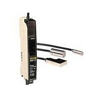
E2CY-X1R5A
Description
Proximity Sensors NON-FERROUS PROX HEA D M5
Manufacturer
Omron
Series
E2CYr
Specifications of E2CY-X1R5A
Maximum Operating Temperature
+ 55 C
Operating Supply Voltage
10 V to 30 V
Sensing Distance
1.5 mm
Minimum Operating Temperature
- 10 C
Sensor Type
Inductive
Sensing Object
Metallic
Response Frequency
-
Material - Body
Stainless Steel
Shielding
Shielded
Voltage - Supply
-
Output Type
-
Terminal Type
3-Wire
Package / Case
Cylinder, Threaded - M5
Lead Free Status / Rohs Status
Lead free / RoHS Compliant


Ratings and Specifications
Sensors
*1. The average value when using the DC-switching control output on the
*2. E2CY-C1R5A-1: ±15% max. of sensing distance at 23°C
*3. When extending the cable, use a 1.5D-2V (equivalent to JIS C 3501) cable
Item
Stable sensing
distance
Differential
travel
Detectable
object
Standard
sensing object
Response
frequency *1
Ambient tem-
perature range
Ambient
humidity range
Temper-
ature
influ-
ence
Vibration
resistance
Shock
resistance
Degree of
protection
Connection
method
Cable length
compensation
Weight
(packed state)
Mate-
rials
Amplifier Unit.
Measurement conditions are as follows: standard sensing object, a distance
of twice the standard sensing object, and a set distance of half the stable
sensing distance.
with characteristic impedance of 50 Ω.
−10 to
55°C
0 to
40°C
Case
Sens-
ing
surface
Cable
Clamp-
ing nut
Toothed
washer
Model
E2CY-X1R5A
E2CY-C1R5A-1
0 to 1.5 mm
10% max. of sensing distance with Amplifier Unit
in FINE mode
10% max. of sensing distance with Amplifier Unit
in NORM mode
Non-ferrous metal
Aluminum: 8 × 8 × 1 mm
40 Hz min. with Amplifier Unit in FINE mode
100 Hz min. with Amplifier Unit in NORM mode
Operating: −10 to 55°C, Storage: −25 to 70°C,
(with no icing or condensation)
Operating/Storage: 35% to 95% (with no conden-
sation)
±15% max. of
sensing dis-
tance at 23°C
±10% max. of
sensing dis-
tance at
23°C*2
Destruction: 10 to 500 Hz, 2-mm double ampli-
tude or 150 m/s
directions
Destruction: 500 m/s
directions
IEC 60529 IP67
Pre-wired Models (High-frequency coaxial cable,
Standard cable length: 3 m)
0.5 to 5 m*3
Approx. 35 g
Stainless steel
Heat-resistant ABS (E2CY-C2AF: Fluororesin)
Soft PVC (E2CY-C2AF: Fluororesin)
Nickel-plated brass (E2CY-X1R5A only)
Zinc-plated iron (E2CY-X1R5A only)
2
0 to 2 mm
±10% max. of
sensing dis-
tance at 23°C
for 2 hours each in X, Y, and Z
E2CY-C2A(F)
2
3 times each in X, Y, and Z
0 to 3 mm
Aluminum:
12 × 12 × 1 mm
±15% max. of
sensing dis-
tance at 23°C
±10% max. of
sensing dis-
tance at 23°C
Zinc die-cast
E2CY-V3A
Amplifier Units
Item
Power supply
voltage
(operating
voltage range)
Current
consumption
Sensing dis-
tance adjust-
ment range
Adjustment
method
Con-
trol
output
Self-diagnos-
tic output
Operation
mode
Protection
circuits
Teaching func-
tion monitor
Indicators
Ambient tem-
perature range
Ambient
humidity
range
Temperature
influence
Voltage
influence
Insulation
resistance
Dielectric
strength
Vibration
resistance
Shock
resistance
Degree of
protection
Connection
method
Cable length
compensation
Weight
(packed state)
Mate-
rials
Accessories
Load
cur-
rent
Resid-
ual
volt-
age
Case
Cover
Model
12 to 24 VDC (10 to 30 VDC), ripple (p-p): 10%
max.
40 mA max.
10% max. of stable sensing distance
Teaching
NPN open collector, 100 mA max. (30 VDC max.)
1 V max. (Load current: 100 mA, Cable length:
2 m)
NPN open collector, 100 mA max. (30 VDC max.)
Changed with NO/NC switch.
Reverse polarity protection, Load short-circuit
protection, Surge suppressor (control and diag-
nostic outputs)
Orange and green indicators (Also used for oper-
ation and excess gain level indicators.)
Operation indicator: Orange
Excess gain level indicators:
Green with sensing object approaching
Orange with sensing object not approaching
Fine-tuning indicator: Green
Operating: −10 to 55°C, Storage: −25 to 70°C,
(with no icing or condensation)
Operating/Storage: 35% to 85%
(with no condensation)
±10% max. of sensing distance at 23°C in the
temperature range of −10 to 55°C
±1% max. of sensing distance in the rated voltage
range ±10%
50 MΩ min. (at 500 VDC) between current-carry-
ing parts and case
1,000 VAC, 50/60 Hz for 1 min between current-
carrying parts and case
Destruction: 10 to 150 Hz, 1.5-mm double ampli-
tude or 100 m/s
directions
Destruction: 300 m/s
directions
IEC 60529 IP50 (with Sensor cable connected
and protective cover attached)
Pre-wired Models (Standard cable length: 2 m)
0.5 to 5 m for cable extension of free-cut length
Approx. 75 g
PBT
Polycarbonate
Mounting Bracket, instruction manual
2
for 2 hours each in X, Y, and Z
E2CY-T11
2
3 times each in X, Y, and Z
E2CY
2
Related parts for E2CY-X1R5A
Image
Part Number
Description
Manufacturer
Datasheet
Request
R

Part Number:
Description:
AMP 12-24VDC 3-WIRE NPN FOR E2CY
Manufacturer:
Omron
Datasheet:

Part Number:
Description:
Proximity Sensors NON-FERROUS PROX HEA D FLAT
Manufacturer:
Omron
Datasheet:
Part Number:
Description:
Proximity Sensors NON-FERROUS PROX HEA D 8MM DMTR
Manufacturer:
Omron
Datasheet:
Part Number:
Description:
Proximity Sensors E2CY-C1R5A SPECIAL W 3M CABLE
Manufacturer:
Omron

Part Number:
Description:
G6S-2GLow Signal Relay
Manufacturer:
Omron Corporation
Datasheet:
Part Number:
Description:
Compact, Low-cost, SSR Switching 5 to 20 A
Manufacturer:
Omron Corporation
Datasheet:
Part Number:
Description:
Manufacturer:
Omron Corporation
Datasheet:
Part Number:
Description:
Manufacturer:
Omron Corporation
Datasheet:
Part Number:
Description:
Manufacturer:
Omron Corporation
Datasheet:
Part Number:
Description:
Manufacturer:
Omron Corporation
Datasheet: