20-101-1132 Rabbit Semiconductor, 20-101-1132 Datasheet - Page 25
20-101-1132
Manufacturer Part Number
20-101-1132
Description
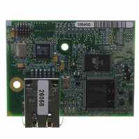
MODULE RCM4210 RABBITCORE
Manufacturer
Rabbit Semiconductor
Datasheet
1.20-101-1132.pdf
(134 pages)
Specifications of 20-101-1132
Module/board Type
MPU Core Module
Product
Microcontroller Modules
Core Processor
Rabbit 4000
Flash
512 KBytes
Operating Supply Voltage
3 to 3.6 V
Board Size
61 mm x 47 mm x 21 mm
Cpu Core
Rabbit 4000
For Use With/related Products
RCM4210
Lead Free Status / RoHS Status
Lead free / RoHS Compliant
Other names
316-1125


3.2.2 Serial Communication
The following sample programs are found in the
•
•
•
User’s Manual
FLOWCONTROL.C
CTS/RTS flow control with serial data coming from Serial Port C (TxC) at 115,200 bps.
The serial data received are displayed in the
To set up the Prototyping Board, you will need to tie TxD and RxD
together on the RS-232 header at J4, and you will also tie TxC and
RxC together using the jumpers supplied in the Development Kit as
shown in the diagram.
A repeating triangular pattern should print out in the
The program will periodically switch flow control on or off to demonstrate the effect of
flow control.
If you have two Prototyping Boards with modules, run this sample program on the
sending board, then disconnect the programming cable and reset the sending board so
that the module is operating in the Run mode. Connect TxC, TxD, and GND on the
sending board to RxC, RxD, and GND on the other board, then, with the programming
cable attached to the other module, run the sample program.
PARITY.C
repeatedly sending byte values 0–127 from Serial Port C to Serial Port D.
The program will switch between generating parity or not on Serial
Port C. Serial Port D will always be checking parity, so parity errors
should occur during every other sequence.
To set up the Prototyping Board, you will need to tie TxC and RxD together on the
RS-232 header at J4 using one of the jumpers supplied in the Development Kit as
shown in the diagram.
The Dynamic C
SERDMA.C
buffer to the serial port and vice versa. The Dynamic C
clear the buffer.
Before you compile and run the sample program, you
will need to connect the RS-232 header at J4 to your PC
as shown in the diagram using the serial to DB9 cable
supplied in the Development Kit.
Once you have compiled and run the sample program,
start Tera Term or another terminal emulation program
to connect to the selected PC serial port at a baud rate of
115,200 bps. You can observe the output in the Dynamic C
STDIO window as you type in Tera Term, and you can
also use the Dynamic C STDIO window to clear the
buffer.
The Tera Term utility can be downloaded from
hp.vector.co.jp/authors/VA002416/teraterm.html.
—This program demonstrates the use of parity modes by
— This program demonstrates using DMA to transfer data from a circular
STDIO
—This program demonstrates how to configure Serial Port D for
window will display the error sequence.
STDIO
SAMPLES\RCM4200\SERIAL
window.
STDIO
STDIO
window.
window is used to view or
folder.
19
Related parts for 20-101-1132
Image
Part Number
Description
Manufacturer
Datasheet
Request
R

Part Number:
Description:
COMPUTER SGL-BRD BL2500 29.4MHZ
Manufacturer:
Rabbit Semiconductor
Datasheet:

Part Number:
Description:
COMPUTER SGL-BRD BL2500 29.4MHZ
Manufacturer:
Rabbit Semiconductor
Datasheet:

Part Number:
Description:
DISPLAY GRAPHIC 12KEY PROG OP670
Manufacturer:
Rabbit Semiconductor
Datasheet:
Part Number:
Description:
DISPLAY GRAPHIC 12KEY ETH OP6700
Manufacturer:
Rabbit Semiconductor
Datasheet:

Part Number:
Description:
COMPUTER SINGLE-BOARD BL2030
Manufacturer:
Rabbit Semiconductor
Part Number:
Description:
COMPUTER SGL-BOARD ETH BL2010
Manufacturer:
Rabbit Semiconductor

Part Number:
Description:
MODULE OP6810 W/O ETH/MEM EXPANS
Manufacturer:
Rabbit Semiconductor
Datasheet:
Part Number:
Description:
COMPUTER SINGLE-BOARD BL2020
Manufacturer:
Rabbit Semiconductor
Part Number:
Description:
COMPUTER BL2010 W/FRICTION LOCK
Manufacturer:
Rabbit Semiconductor
Part Number:
Description:
COMPUTER BL2020 W/FRICTION LOCK
Manufacturer:
Rabbit Semiconductor
Part Number:
Description:
COMPUTER SGL-BRD BL2500 44.2MHZ
Manufacturer:
Rabbit Semiconductor
Datasheet:
Part Number:
Description:
COMPUTER SGL-BOARD FULL BL2000
Manufacturer:
Rabbit Semiconductor

Part Number:
Description:
COMPUTER SINGLE-BOARD BL2110
Manufacturer:
Rabbit Semiconductor

Part Number:
Description:
COMPUTER SGL-BRD 29.4MHZ BL2610
Manufacturer:
Rabbit Semiconductor
Datasheet:
Part Number:
Description:
INTERFACE OP6800 512K FLASH&SRAM
Manufacturer:
Rabbit Semiconductor
Datasheet: