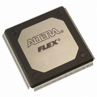
EPM9560ARI240-10 Altera, EPM9560ARI240-10 Datasheet - Page 29

EPM9560ARI240-10
Manufacturer Part Number
EPM9560ARI240-10
Description
IC MAX 9000 CPLD 560 240-RQFP
Manufacturer
Altera
Series
MAX® 9000r
Datasheet
1.EPM9320LC84-15.pdf
(46 pages)
Specifications of EPM9560ARI240-10
Programmable Type
In System Programmable
Delay Time Tpd(1) Max
10.0ns
Voltage Supply - Internal
4.5 V ~ 5.5 V
Number Of Logic Elements/blocks
35
Number Of Macrocells
560
Number Of Gates
12000
Number Of I /o
191
Operating Temperature
-40°C ~ 85°C
Mounting Type
Surface Mount
Package / Case
240-RQFP
Voltage
3.3V/5V
Memory Type
EEPROM
Number Of Logic Elements/cells
35
Family Name
MAX 9000
# Macrocells
560
Number Of Usable Gates
12000
Frequency (max)
144.9MHz
Propagation Delay Time
10ns
Number Of Logic Blocks/elements
35
# I/os (max)
191
Operating Supply Voltage (typ)
5V
In System Programmable
Yes
Operating Supply Voltage (min)
4.5V
Operating Supply Voltage (max)
5.5V
Operating Temp Range
-40C to 85C
Operating Temperature Classification
Industrial
Mounting
Surface Mount
Pin Count
240
Package Type
RQFP
Lead Free Status / RoHS Status
Contains lead / RoHS non-compliant
Features
-
Lead Free Status / Rohs Status
Not Compliant
Other names
544-2365
Available stocks
Company
Part Number
Manufacturer
Quantity
Price
Company:
Part Number:
EPM9560ARI240-10
Manufacturer:
ALTERA
Quantity:
6
Part Number:
EPM9560ARI240-10
Manufacturer:
ALTERA/阿尔特拉
Quantity:
20 000
Notes to tables:
(1)
(2)
(3)
(4)
(5)
(6)
(7)
(8)
(9)
(10) Capacitance is sample-tested only and is measured at 25 C.
(11) Measured with a 16-bit loadable, enabled, up/down counter programmed into each LAB. I
Figure 13. Output Drive Characteristics of MAX 9000 Devices
Note:
(1)
Altera Corporation
Symbol
I
Typical I
Output
Current (mA)
CC1
5.0-V
Table 20. MAX 9000A Device Typical I
See the
Minimum DC input on I/O pins is –0.5 V and on the four dedicated input pins is –0.3 V. During transitions, the
inputs may undershoot to –2.0 V or overshoot to 7.0 V for periods shorter than 20 ns under no-load conditions.
V
Numbers in parentheses are for industrial-temperature-range devices.
Typical values are for T
These values are specified under the MAX 9000 recommended operating conditions, shown in
During in-system programming, the minimum V
during JTAG testing remains at 2.0 V. To attain this 3.6-V V
ByteBlasterMV download cables must have a 5.0-V V
This parameter is measured with 50% of the outputs each sinking 12 mA. The I
TTL or CMOS output current; the I
JTAG pin input leakage is typically –60
Output drive characteristics include the JTAG TDO pin.
CC
O
must rise monotonically.
I
standby, typical)
CC
150
120
Operating Requirements for Altera Devices Data
90
60
30
supply current (low-power mode,
Parameter
1
Output Voltage (V)
A
2
= 25 C and V
Figure 13
with 5.0-V and 3.3-V V
V
Room Temperature
I
I
OH
3
OL
CCIO
OL
= 5.0 V
parameter refers to the low-level TTL or CMOS output current.
shows typical output drive characteristics for MAX 9000 devices
4
CC
CC
V
Supply Current Values
I
.
= 5.0 V.
= ground, no load
5
MAX 9000 Programmable Logic Device Family Data Sheet
IH
of the JTAG TCK pin is 3.6 V. The minimum V
Sheet.
CC
CCIO
Conditions
.
3.3-V
Typical I
Output
Current (mA)
IH
.
(11)
during programming, the ByteBlaster and
O
Note (1)
150
120
90
60
30
1
OH
EPM9320A EPM9560A Unit
parameter refers to high-level
Output Voltage (V)
2
99
V
Room Temperature
I
I
CC
OH
3
OL
CCIO
3.3
Table 15 on page
is measured at 0 C.
= 3.3 V
IH
4
174
of this pin
5
mA
27.
29


