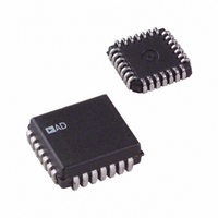
AD7225KP-REEL Analog Devices Inc, AD7225KP-REEL Datasheet - Page 17

AD7225KP-REEL
Manufacturer Part Number
AD7225KP-REEL
Description
IC DAC 8BIT QUAD W/AMP 28-PLCC
Manufacturer
Analog Devices Inc
Datasheet
1.AD7225CRSZ.pdf
(24 pages)
Specifications of AD7225KP-REEL
Rohs Status
RoHS non-compliant
Settling Time
4µs
Number Of Bits
8
Number Of Converters
4
Voltage Supply Source
Dual ±
Power Dissipation (max)
500mW
Operating Temperature
-40°C ~ 85°C
Mounting Type
Surface Mount
Package / Case
28-LCC (J-Lead)
Data Interface
-
Available stocks
Company
Part Number
Manufacturer
Quantity
Price
Company:
Part Number:
AD7225KP-REEL
Manufacturer:
Analog Devices Inc
Quantity:
10 000
APPLICATIONS INFORMATION
PROGRAMMABLE TRANSVERSAL FILTER
A discrete time filter can be described by either multiplication
in the frequency domain or by convolution in the time domain:
The convolution sum can be implemented using the special struc-
ture known as the transversal filter (see Figure 21). It consists
of an N-stage delay line with N taps weighted by N coefficients,
the resulting products being accumulated to form the output.
The tap weights or coefficients h
the impulse response and therefore determine the filter transfer
function. A particular filter frequency response is realized by
setting the coefficients to the appropriate values. This property
leads to the implementation of transversal filters whose fre-
quency response is programmable.
A four-tap programmable transversal filter can be implemented
using the AD7225 (see Figure 20). The input signal is first sampled
and converted to allow the tapped delay line function to be
provided by the AM29520. The multiplication of delayed input
samples by fixed, programmable up weights is accomplished by
the AD7225, the four coefficients or reference inputs being set
by the digital codes stored in the AD7226. The resultant products
are accumulated to yield the convolution sum output sample,
which is held by the AD585.
FILTER
INPUT
Y
( )
ω
h
1
=
1
X
H
AD7820
n
AD584
ADC
( ) ( )
REF
ω
T
h
2
X
X
2
Figure 21. Transversal Filter
ω
n – 1
10V
SAMPLES
INPUT
or
T
V
h
y
REF
3
n
X
=
3
n – 2
AM29520
+
GAIN SET
AM7224
∑
k
OUTPUT
N
FILTER
=
k
DAC
TLC
1
are the nonzero elements of
h
k
X
h
n
N – 1
−
V
DELAYED
SAMPLES
N –1
k
OUT
INPUT
+
X
1
y
n – N
n
V
=
REF
k = 1
h
T
1
N
h
N
V
V
h
Figure 20. Programmable Transversal Filter
k
REF
OUT
X
N
n – N + 1
X
n – k + 1
A
A
h
2
TAP WEIGHT
QUAD DAC
QUAD DAC
AD7225
AD7225
V
V
REF
OUT
Rev. C | Page 17 of 24
A
A
h
3
V
V
REF
OUT
A
A
h
4
Low-pass, band-pass, and high-pass filters can be synthesized
using this arrangement. The particular up weights needed for
any desired transfer function can be obtained using the standard
Remez exchange algorithm. Figure 22 shows the theoretical
low-pass frequency response produced by a four-tap transversal
filter with the coefficients indicated. Although the theoretical
prediction does not take into account the quantization of the
input samples and the truncation of the coefficients, neverthe-
V
V
V
V
V
V
REF
OUT
OUT
OUT
OUT
OUT
A
A
A
B
C
D
–100
–100
–10
–20
–30
–40
–50
–60
–70
–80
–90
–10
–20
–30
–40
–50
–60
–70
–80
–90
FILTER
0
0
INPUT
0
0
0.05
0.05
+
h
ACCUMULATOR
1
Figure 22. Predicted (Theoretical) Response
OUTPUT
1
X
0.10
0.10
n
Figure 23. Actual Response
NORMALIZED FREQUENCY (f/f
T
0.15
0.15
h
AD585
2
SHA
X
h
h
h
h
n – 1
1
2
3
4
2
FREQUENCY (f/f
(DAC A) = 00011110
(DAC B) = 01101011
(DAC C) = 01101011
(DAC D) = 00011110
0.20
0.20
OUTPUT
FILTER
T
+
0.25
0.25
h
OUTPUT
3
FILTER
X
n – 2
3
0.30
0.30
S
)
T
0.35
0.35
h
4
y(n)
X
S
n – 3
4
)
0.40
0.40
h
h
h
h
1
2
3
4
0.45
0.45
= 0.117
= 0.417
= 0.417
= 0.417
AD7225
0.50
0.50


