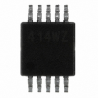
ISL22414WFU10Z Intersil, ISL22414WFU10Z Datasheet - Page 5

ISL22414WFU10Z
Manufacturer Part Number
ISL22414WFU10Z
Description
IC POT DGTL 256TP LN LP 10-MSOP
Manufacturer
Intersil
Series
XDCP™r
Datasheet
1.ISL22414WFU10Z.pdf
(16 pages)
Specifications of ISL22414WFU10Z
Taps
256
Resistance (ohms)
10K
Number Of Circuits
1
Temperature Coefficient
±50ppm/°C
Memory Type
Non-Volatile
Interface
SPI Serial
Voltage - Supply
±2.25 V ~ 5.5 V
Operating Temperature
-40°C ~ 125°C
Mounting Type
Surface Mount
Package / Case
10-MSOP, Micro10™, 10-uMAX, 10-uSOP
Resistance In Ohms
10K
Lead Free Status / RoHS Status
Lead free / RoHS Compliant
Available stocks
Company
Part Number
Manufacturer
Quantity
Price
Company:
Part Number:
ISL22414WFU10Z
Manufacturer:
Intersil
Quantity:
500
Company:
Part Number:
ISL22414WFU10Z-T7A
Manufacturer:
INTERSIL
Quantity:
1 001
Operating Specifications
EEPROM SPECIFICATION
SERIAL INTERFACE SPECIFICATIONS
Hysteresis
VccRamp
SYMBOL
(Note 16)
t
ShdnRec
I
LkgDig
I
I
t
Vpor
V-SD
V
V-SB
WRT
t
I
V
V
WC
SD
t
OL
D
IH
IL
V- Current (Standby)
V
V- Current (Shutdown)
Leakage Current, at Pins SCK, SDI,
SDO and CS
DCP Wiper Response Time
DCP Recall Time From Shutdown
Mode
Power-on Recall Voltage
V
Power-up Delay
EEPROM Endurance
EEPROM Retention
Non-volatile Write Cycle Time
voltage
Voltage
Hysteresis
SDO Output Buffer LOW Voltage
SCK, SDI, and CS Input Buffer LOW
SCK, SDI, and CS Input Buffer HIGH
SCK, SDI, and CS Input Buffer
CC
CC
Current (Shutdown)
Ramp Rate
PARAMETER
5
Over the recommended operating conditions unless otherwise specified. Boldface limits apply over the
operating temperature range. (Continued)
V- = -5.5V, V
in standby state
V- = -5.5V, V
interface in standby state
V- = -2.25V, V
interface in standby state
V- = -2.25V, V
interface in standby state
V
in standby state
V
interface in standby state
V
interface in standby state
V
interface in standby state
V- = -5.5V, V
in standby state
V- = -5.5V, V
interface in standby state
V- = -2.25V, V
interface in standby state
V- = -2.25V, V
interface in standby state
Voltage at pin from GND to V
CS rising edge to wiper new position
CS rising edge to wiper stored position and RH
connection
Minimum V
V
recall completed, and SPI Interface in standby
state
Temperature T ≤ +55ºC
I
voltage Vpu = V
OL
CC
CC
CC
CC
CC
= 4mA for Open Drain output, pull-up
= +5.5V, V- = -5.5V @ +85°C, SPI interface
= +5.5V, V- = -5.5V @ +125°C, SPI
= +2.25V, V- = -2.25V @ +85°C, SPI
= +2.25V, V- = -2.25V @ +125°C, SPI
above Vpor, to DCP Initial Value Register
CC
CC
CC
ISL22414
CC
CC
TEST CONDITIONS
CC
CC
CC
CC
at which memory recall occurs
= +5.5V @ +85°C, SPI interface
= +5.5V @ +85°C, SPI interface
CC
= +5.5V @ +125°C, SPI
= +5.5V @ +125°C, SPI
= +2.25V @ +85°C, SPI
= +2.25V @ +125°C, SPI
= +2.25V @ +85°C, SPI
= +2.25V @ +125°C, SPI
CC
1,000,000
(Note 18)
0.05*V
0.7*V
MIN
-2.5
-1.5
-2.5
-1.5
-0.5
-0.3
1.9
0.2
50
-4
-3
-4
-3
0
CC
CC
(Note 4)
TYP
-0.7
-0.3
-0.7
-0.3
1.5
0.2
0.1
0.5
1.5
12
-3
-1
-3
-1
1
(Note 18)
V
0.3*V
CC
MAX
1.5
2.5
0.5
2.1
0.4
20
1
2
5
+0.3
CC
December 16, 2010
Cycles
Years
UNIT
V/ms
FN6424.1
ms
ms
µA
µA
µA
µA
µA
µA
µA
µA
µA
µA
µA
µA
µA
µs
µs
V
V
V
V
V


