LTC2215IUP#PBF Linear Technology, LTC2215IUP#PBF Datasheet - Page 22
LTC2215IUP#PBF
Manufacturer Part Number
LTC2215IUP#PBF
Description
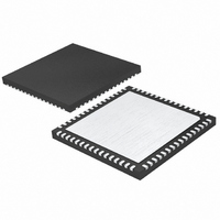
IC ADC 16BIT 65MSPS 64-QFN
Manufacturer
Linear Technology
Datasheet
1.LTC2216CUPPBF.pdf
(36 pages)
Specifications of LTC2215IUP#PBF
Number Of Bits
16
Sampling Rate (per Second)
65M
Data Interface
Parallel
Number Of Converters
1
Power Dissipation (max)
1.25W
Voltage Supply Source
Single Supply
Operating Temperature
-40°C ~ 85°C
Mounting Type
Surface Mount
Package / Case
64-WFQFN, Exposed Pad
Lead Free Status / RoHS Status
Lead free / RoHS Compliant
Available stocks
Company
Part Number
Manufacturer
Quantity
Price


APPLICATIONS INFORMATION
LTC2216/LTC2215
22
The LTC2216/LTC2215 are CMOS pipelined multistep convert-
ers with a low noise front-end. As shown in Figure 1, these
converters have fi ve pipelined ADC stages; a sampled analog
input will result in a digitized value seven cycles later (see the
Timing Diagram section). The analog input is differential for
improved common mode noise immunity and to maximize
the input range. Additionally, the differential input drive
will reduce even order harmonics of the sample and hold
circuit. The encode input is also differential for improved
common mode noise immunity.
The LTC2216/LTC2215 have two phases of operation, deter-
mined by the state of the differential ENC
For brevity, the text will refer to ENC
ENC high and ENC
Each pipelined stage shown in Figure 1 contains an ADC,
a reconstruction DAC and an interstage amplifi er. In
operation, the ADC quantizes the input to the stage and
the quantized value is subtracted from the input by the
DAC to produce a residue. The residue is amplifi ed and
output by the residue amplifi er. Successive stages oper-
ate out of phase so that when odd stages are outputting
their residue, the even stages are acquiring that residue
and vice versa.
When ENC is low, the analog input is sampled differen-
tially directly onto the input sample-and-hold capacitors,
inside the “input S/H” shown in the block diagram. At the
instant that ENC transitions from low to high, the voltage
on the sample capacitors is held. While ENC is high, the
held input voltage is buffered by the S/H amplifi er which
drives the fi rst pipelined ADC stage. The fi rst stage acquires
the output of the S/H amplifi er during the high phase of
ENC. When ENC goes back low, the fi rst stage produces
its residue which is acquired by the second stage. At the
same time, the input S/H goes back to acquiring the analog
input. When ENC goes high, the second stage produces
its residue which is acquired by the third stage. An identi-
cal process is repeated for the third and fourth stages,
resulting in a fourth stage residue that is sent to the fi fth
stage for fi nal evaluation.
Each ADC stage following the fi rst has additional range to
accommodate fl ash and amplifi er offset errors. Results
CONVERTER OPERATION
+
less than ENC
+
–
greater than ENC
as ENC low.
+
/ENC
–
input pins.
–
as
from all of the ADC stages are digitally delayed such that
the results can be properly combined in the correction
logic before being sent to the output buffer.
SAMPLE/HOLD OPERATION AND INPUT DRIVE
Sample/Hold Operation
Figure 2 shows an equivalent circuit for the LTC2216/
LTC2215 CMOS differential sample and hold. The differ-
ential analog inputs are sampled directly onto sampling
capacitors (C
capacitors shown attached to each input (C
the summation of all other capacitance associated with
each input.
During the sample phase when ENC is low, the NMOS
transistors connect the analog inputs to the sampling
capacitors and they charge to, and track the differential
input voltage. When ENC transitions from low to high, the
sampled input voltage is held on the sampling capacitors.
During the hold phase when ENC is high, the sampling
capacitors are disconnected from the input and the held
voltage is passed to the ADC core for processing. As ENC
transitions for high to low, the inputs are reconnected to
ENC
ENC
A
A
IN
IN
+
+
–
–
LTC2216/LTC2215
1.6V
1.6V
V
DD
6k
6k
SAMPLE
Figure 2. Equivalent Input Circuit
V
DD
R
R
PARASITIC
PARASITIC
) through NMOS transistors. The
3Ω
3Ω
V
DD
C
1.8pF
C
1.8pF
PARASITIC
PARASITIC
20Ω
20Ω
R
R
ON
ON
PARASITIC
C
C
SAMPLE
SAMPLE
7.3pF
7.3pF
22165 F02
) are
22165f
Related parts for LTC2215IUP#PBF
Image
Part Number
Description
Manufacturer
Datasheet
Request
R

Part Number:
Description:
CD ROM LINEARVIEW DATASHEETS
Manufacturer:
Linear Technology

Part Number:
Description:
Standalone Linear Li-Ion Battery Charger with Thermal Regulation in ThinSOT
Manufacturer:
Linear Technology Corporation
Datasheet:
Part Number:
Description:
Low noise, high frequency, 8th order linear phase lowpass filter
Manufacturer:
Linear Technology Corporation
Datasheet:
Part Number:
Description:
Manufacturer:
Linear Technology Corporation
Datasheet:
Part Number:
Description:
Manufacturer:
Linear Technology Corporation
Datasheet:
Part Number:
Description:
Manufacturer:
Linear Technology Corporation
Datasheet:
Part Number:
Description:
Manufacturer:
Linear Technology Corporation
Datasheet:
Part Number:
Description:
Manufacturer:
Linear Technology Corporation
Datasheet:
Part Number:
Description:
Manufacturer:
Linear Technology Corporation
Datasheet:
Part Number:
Description:
Manufacturer:
Linear Technology Corporation
Datasheet:
Part Number:
Description:
Dual and Quad, JFET Input Precision High Speed Op Amps
Manufacturer:
Linear Technology Corporation
Datasheet:
Part Number:
Description:
Manufacturer:
Linear Technology Corporation
Datasheet:
Part Number:
Description:
1, 2, 6 and 8 Channel, 10-Bit Serial I/O Data Acquisition Systems
Manufacturer:
Linear Technology Corporation
Datasheet:
Part Number:
Description:
Manufacturer:
Linear Technology Corporation
Datasheet:
Part Number:
Description:
Universal dual filter building block
Manufacturer:
Linear Technology Corporation
Datasheet: