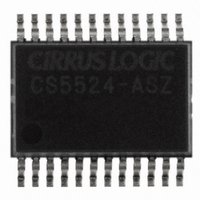
CS5524-ASZ Cirrus Logic Inc, CS5524-ASZ Datasheet - Page 2

CS5524-ASZ
Manufacturer Part Number
CS5524-ASZ
Description
IC ADC 24BIT 4CH 20SSOP
Manufacturer
Cirrus Logic Inc
Specifications of CS5524-ASZ
Number Of Converters
1
Package / Case
24-SSOP
Number Of Bits
24
Data Interface
Serial
Power Dissipation (max)
14.8mW
Voltage Supply Source
Analog and Digital
Operating Temperature
-40°C ~ 85°C
Mounting Type
Surface Mount
Number Of Adc Inputs
4
Architecture
Delta-Sigma
Conversion Rate
617 SPs
Resolution
24 bit
Input Type
Voltage
Interface Type
Serial (3-Wire)
Voltage Reference
2.5 V
Supply Voltage (max)
5 V
Supply Voltage (min)
25 mV
Maximum Power Dissipation
500 mW
Maximum Operating Temperature
+ 85 C
Mounting Style
SMD/SMT
Input Voltage
25 mV to 5 V
Minimum Operating Temperature
- 40 C
Lead Free Status / RoHS Status
Lead free / RoHS Compliant
For Use With
598-1012 - EVAL BOARD FOR CS5524 ADC
Lead Free Status / Rohs Status
Lead free / RoHS Compliant
Other names
598-1106-5
Available stocks
Company
Part Number
Manufacturer
Quantity
Price
Part Number:
CS5524-ASZ
Manufacturer:
CIRRUS
Quantity:
20 000
TABLE OF CONTENTS
Contacting Cirrus Logic Support
For all product questions and inquiries contact a Cirrus Logic Sales Representative.
To find the one nearest to you go to
IMPORTANT NOTICE
Cirrus Logic, Inc. and its subsidiaries (“Cirrus”) believe that the information contained in this document is accurate and reliable. However, the information is subject to
change without notice and is provided “AS IS” without warranty of any kind (express or implied). Customers are advised to obtain the latest version of relevant infor
mation to verify, before placing orders, that information being relied on is current and complete. All products are sold subject to the terms and conditions of sale supplied
at the time of order acknowledgment, including those pertaining to warranty, indemnification, and limitation of liability. No responsibility is assumed by Cirrus for the
use of this information, including use of this information as the basis for manufacture or sale of any items, or for infringement of patents or other rights of third parties
This document is the property of Cirrus and by furnishing this information, Cirrus grants no license, express or implied under any patents, mask work rights, copyrights
trademarks, trade secrets or other intellectual property rights. Cirrus owns the copyrights associated with the information contained herein and gives consent for copies
to be made of the information only for use within your organization with respect to Cirrus integrated circuits or other products of Cirrus. This consent does not extend
to other copying such as copying for general distribution, advertising or promotional purposes, or for creating any work for resale.
CERTAIN APPLICATIONS USING SEMICONDUCTOR PRODUCTS MAY INVOLVE POTENTIAL RISKS OF DEATH, PERSONAL INJURY, OR SEVERE PROPER
TY OR ENVIRONMENTAL DAMAGE (“CRITICAL APPLICATIONS”). CIRRUS PRODUCTS ARE NOT DESIGNED, AUTHORIZED OR WARRANTED FOR USE IN
AIRCRAFT SYSTEMS, MILITARY APPLICATIONS, PRODUCTS SURGICALLY IMPLANTED INTO THE BODY, AUTOMOTIVE SAFETY OR SECURITY DEVICES
LIFE SUPPORT PRODUCTS OR OTHER CRITICAL APPLICATIONS. INCLUSION OF CIRRUS PRODUCTS IN SUCH APPLICATIONS IS UNDERSTOOD TO BE
FULLY AT THE CUSTOMER'S RISK AND CIRRUS DISCLAIMS AND MAKES NO WARRANTY, EXPRESS, STATUTORY OR IMPLIED, INCLUDING THE IMPLIED
WARRANTIES OF MERCHANTABILITY AND FITNESS FOR PARTICULAR PURPOSE, WITH REGARD TO ANY CIRRUS PRODUCT THAT IS USED IN SUCH A
MANNER. IF THE CUSTOMER OR CUSTOMER'S CUSTOMER USES OR PERMITS THE USE OF CIRRUS PRODUCTS IN CRITICAL APPLICATIONS, CUSTOM
ER AGREES, BY SUCH USE, TO FULLY INDEMNIFY CIRRUS, ITS OFFICERS, DIRECTORS, EMPLOYEES, DISTRIBUTORS AND OTHER AGENTS FROM ANY
AND ALL LIABILITY, INCLUDING ATTORNEYS' FEES AND COSTS, THAT MAY RESULT FROM OR ARISE IN CONNECTION WITH THESE USES.
Cirrus Logic, Cirrus, and the Cirrus Logic logo designs are trademarks of Cirrus Logic, Inc. All other brand and product names in this document may be trademarks o
service marks of their respective owners.
SPI is a trademark of Motorola, Inc.
2
1. CHARACTERISTICS AND SPECIFICATIONS ........................................................................ 5
2. GENERAL DESCRIPTION ..................................................................................................... 13
ANALOG CHARACTERISTICS ................................................................................................ 5
TYPICAL RMS NOISE, CS5521/23.......................................................................................... 7
TYPICAL NOISE FREE RESOLUTION (BITS), CS5521/23 .................................................... 7
TYPICAL RMS NOISE, CS5522/24/28..................................................................................... 8
TYPICAL NOISE FREE RESOLUTION (BITS), CS5522/24/28 ............................................... 8
5 V DIGITAL CHARACTERISTICS........................................................................................... 9
3 V DIGITAL CHARACTERISTICS........................................................................................... 9
DYNAMIC CHARACTERISTICS ............................................................................................ 10
RECOMMENDED OPERATING CONDITIONS ..................................................................... 10
ABSOLUTE MAXIMUM RATINGS ......................................................................................... 10
SWITCHING CHARACTERISTICS ........................................................................................ 11
2.1 Analog Input ..................................................................................................................... 13
2.2 Overview of ADC Register Structure and Operating Modes ............................................ 16
2.1.1 Instrumentation Amplifier ......................................................................................... 14
2.1.2 Coarse/Fine Charge Buffers ............................................................................... 14
2.1.3 Analog Input Span Considerations .......................................................................... 15
2.1.4 Measuring Voltages Higher than 5 V .................................................................. 15
2.1.5 Voltage Reference .............................................................................................. 16
2.2.1 System Initialization ............................................................................................ 18
2.2.2 Serial Port Initialization Sequence ...................................................................... 18
2.2.3 Command Register Quick Reference
2.2.4 Command Register Descriptions ........................................................................ 20
2.2.5 Serial Port Interface ............................................................................................ 25
2.2.6 Reading/Writing the Offset, Gain, and Configuration Registers .......................... 26
2.2.7 Reading/Writing the Channel-Setup Registers ................................................... 26
2.2.7.1 Latch Outputs ...................................................................................... 28
2.2.7.2 Channel Select Bits ............................................................................. 28
2.2.7.3 Output Word Rate Selection ............................................................... 28
2.2.7.4 Gain Bits .............................................................................................. 28
www.cirrus.com
............................................................... 19
CS5521/22/23/24/28
DS317F4


