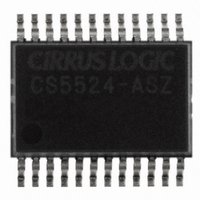
CS5524-ASZ Cirrus Logic Inc, CS5524-ASZ Datasheet - Page 17

CS5524-ASZ
Manufacturer Part Number
CS5524-ASZ
Description
IC ADC 24BIT 4CH 20SSOP
Manufacturer
Cirrus Logic Inc
Specifications of CS5524-ASZ
Number Of Converters
1
Package / Case
24-SSOP
Number Of Bits
24
Data Interface
Serial
Power Dissipation (max)
14.8mW
Voltage Supply Source
Analog and Digital
Operating Temperature
-40°C ~ 85°C
Mounting Type
Surface Mount
Number Of Adc Inputs
4
Architecture
Delta-Sigma
Conversion Rate
617 SPs
Resolution
24 bit
Input Type
Voltage
Interface Type
Serial (3-Wire)
Voltage Reference
2.5 V
Supply Voltage (max)
5 V
Supply Voltage (min)
25 mV
Maximum Power Dissipation
500 mW
Maximum Operating Temperature
+ 85 C
Mounting Style
SMD/SMT
Input Voltage
25 mV to 5 V
Minimum Operating Temperature
- 40 C
Lead Free Status / RoHS Status
Lead free / RoHS Compliant
For Use With
598-1012 - EVAL BOARD FOR CS5524 ADC
Lead Free Status / Rohs Status
Lead free / RoHS Compliant
Other names
598-1106-5
Available stocks
Company
Part Number
Manufacturer
Quantity
Price
Part Number:
CS5524-ASZ
Manufacturer:
CIRRUS
Quantity:
20 000
mentation amplifier, and providing a number of
flags which indicate converter operation.
A group of registers, called Channel Set-up Regis-
ters, are also included in the converters. These reg-
isters are used to hold pre-loaded conversion
instructions. Each channel set-up register is 24 bits
wide and holds two 12-bit conversion instructions
(Setups). Upon power-up, these registers can be
initialized by the user’s microcontroller with con-
version instructions. The user can then use bits in
the configuration register to choose a conversion
mode.
Several conversion modes are possible. Using the
single conversion mode, an 8-bit command word
can be written into the serial port. The command in-
cludes pointer bits which ‘point’ to a 12-bit com-
mand in one of the Channel Setup Registers which
is to be executed. The 12-bit commands can be set-
up to perform a conversion on any of the input
channels of the converter. More than one of the 12-
bit Setups can be used for the same analog input
channel. This allows the user to convert on the
same signal with either a different conversion
speed, a different gain range, or any of the other op-
tions available in the Setup Register. The user can
DS317F4
AIN1
AIN2
AIN3
AIN4
Chop Frequency
Multiple Conversions
Depth Pointer
Loop
Read Convert
Powerdown Modes
Flags
Etc.
4 (24)
Off 1
Off 2
Off 3
Off 4
Configuration
Figure 9. CS5523/24 Register Diagram
1 x 24
Gain 1
Gain 2
Gain 3
Gain 4
4 (24)
set up the registers to perform conversions using
different conversion options on each of the input
channels.
The ADCs also include multiple-channel conver-
sion capability. User bits in the configuration regis-
ter of the ADCs can be configured to sequence
through the 12-bit command Setups, performing a
conversion according to the content of each 12-bit
Setup. This channel scanning capability can be
configured to run continuously, or to scan through
a specified number of Setup Registers and stop un-
til commanded to continue. In the multiple-channel
scanning modes, the conversion data words are
loaded into an on-chip data FIFO. The converter is-
sues a flag on the SDO pin when a scan cycle is
completed so the user can read the FIFO. More de-
tails are given in the following pages.
Instructions are provided on how to initialize the
converter, perform offset and gain calibrations, and
to configure the converter for the various conver-
sion modes. Each of the bits of the configuration
register and of the Channel Setup Registers is de-
scribed. A list of examples follows the description
section. Table 2 can be used to decode all valid
commands (the first 8 bits into the serial port).
Setup 1
Setup 3
Setup 5
Setup 7
4 (12 x 2)
Latch Outputs
Channel Select
Output Word Rate
PGA Selection
Unipolar/Bipolar
Setup 2
Setup 4
Setup 6
Setup 8
CS5521/22/23/24/28
8 x 24
DATA
FIFO
SDO
17


