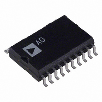
AD73311LAR-REEL Analog Devices Inc, AD73311LAR-REEL Datasheet - Page 19

AD73311LAR-REEL
Manufacturer Part Number
AD73311LAR-REEL
Description
IC ANALOG FRONT END 20-SOIC T/R
Manufacturer
Analog Devices Inc
Datasheet
1.AD73311LAR.pdf
(36 pages)
Specifications of AD73311LAR-REEL
Rohs Status
RoHS non-compliant
Number Of Bits
16
Number Of Channels
2
Power (watts)
50mW
Voltage - Supply, Analog
3V
Voltage - Supply, Digital
3V
Package / Case
20-SOIC (7.5mm Width)
When using the indirectly coupled frame sync configuration in
cascaded operation it is necessary to be aware of the restrictions
in sending data to all devices in the cascade. Effectively the time
allowed is given by the sampling interval (256/DMCLK) which
is 15.625 µs for a sample rate of 64 kHz. In this interval, the
DSP must transfer N × 16 bits of information where N is the
number of devices in the cascade. Each bit will take 1/SCLK
and, allowing for any latency between the receipt of the Rx
interrupt and the transmission of the Tx data, the relationship
for successful operation is given by:
The interrupt latency will include the time between the ADC
sampling event and the Rx interrupt being generated in the
DSP—this should be 16 SCLK cycles.
In Cascade Mode, each device must know the number of devices
in the cascade because the Data and Mixed modes use a method
of counting input frame sync pulses to decide when they should
update the DAC register from the serial input register. Control
Register A contains a 3-bit field (DC0–2) that is programmed
by the DSP during the programming phase. The default condi-
tion is that the field contains 000b, which is equivalent to a
single device in cascade (see Table XVIII). However, for cascade
operation this field must contain a binary value that is one less
than the number of devices in the cascade.
DC2
0
0
0
0
1
1
1
1
PERFORMANCE
As the AD73311L is designed to provide high performance, low
cost conversion, it is important to understand the means by
which this high performance can be achieved in a typical applica-
tion. This section will, by means of spectral graphs, outline the
typical performance of the device and highlight some of the
options available to users in achieving their desired sample
rate, either directly in the device or by doing some post-processing
in the DSP, while also showing the advantages and disadvan-
tages of the different approaches.
Encoder Section
The AD73311L offers a variable sampling rate from a fixed
MCLK frequency—with 64 kHz, 32 kHz, 16 kHz and 8 kHz
being available with a 16.384 MHz external clock. Each of these
sampling rates preserves the same sampling rate in the ADC’s
sigma-delta modulator, which ensures that the noise performance
is optimized in each case. The examples below will show the
performance of a 1 kHz sine wave when converted at the various
sample rates.
256/DMCLK > ((N × 16/SCLK) + T
Table XVIII. Device Count Settings
DC1
0
0
1
1
0
0
1
1
DC0
0
1
0
1
0
1
0
1
INTERRUPT LATENCY
Cascade Length
1
2
3
4
5
6
7
8
)
The range of sampling rates is aimed to offer the user a degree
of flexibility in deciding how their analog front end is to be
implemented. The high sample rates of 64 kHz and 32 kHz are
suited to those applications, such as active control, where low
conversion group delay is essential. On the other hand, the
lower sample rates of 16 kHz and 8 kHz are better suited for
applications such as telephony, where the lower sample rates
result in lower DSP overhead.
Figure 15 shows the spectrum of the 1 kHz test tone sampled at
64 kHz. The plot shows the characteristic shaped noise floor of
a sigma-delta converter, which is initially flat in the band of
interest but then rises with increasing frequency. If a suitable
digital filter is applied to this spectrum, it is possible to eliminate
the noise floor in the higher frequencies. This signal can then be
used in DSP algorithms or can be further processed in a deci-
mation algorithm to reduce the effective sample rate. Figure 16
shows the resulting spectrum following the filtering and decima-
tion of the spectrum of Figure 15 from 64 kHz to an 8 kHz rate.
–100
–120
–100
–120
–140
–20
–40
–60
–80
–20
–40
–60
–80
0
0
0
0
500
0.5
1000
1.0
1500
FREQUENCY – Hz
FREQUENCY – Hz
1.5
2000
2.0
2500
2.5
3000
AD73311L
3.0
3500
4000
10
3.5
4


