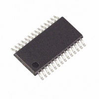
MAXQ3180-RAN+ Maxim Integrated Products, MAXQ3180-RAN+ Datasheet - Page 57

MAXQ3180-RAN+
Manufacturer Part Number
MAXQ3180-RAN+
Description
IC AFE POLYPHASE MULTI 28-TSSOP
Manufacturer
Maxim Integrated Products
Datasheet
1.MAXQ3180-RAN.pdf
(101 pages)
Specifications of MAXQ3180-RAN+
Number Of Channels
8
Power (watts)
35mW
Voltage - Supply, Analog
3.6V
Voltage - Supply, Digital
3.6V
Package / Case
28-TSSOP
For Use With
MAXQ3180-KIT - KIT EV REFRNC DSIGN FOR MAXQ3180
Lead Free Status / RoHS Status
Lead free / RoHS Compliant
Number Of Bits
-
A second problem with updating NS on every line
cycles is the fact that noise impulses that occur at near-
ly the same time as the zero crossing can shift the zero
crossing, affecting the accuracy of the energy mea-
sured during the preceding period. For this reason, a
second register, REJ_NS contains a value that specifies
how far a particular sample can deviate from the aver-
age and still be considered valid. If the period of the
newly acquired DSP cycle differs from the previously
accumulated average value by more than REJ_NS ADC
frames, NS is not updated with the new period (but the
energy is still accumulated).
With this discussion in mind, the signal path for the vari-
ous reported parameters can be reviewed.
RMS Volts and RMS Amps: First, the squared voltage
accumulation is divided by NS. This accomplishes the
“mean” part of the “root-mean-square” calculation.
Then, the square root of the result is taken, producing
the raw RMS calculation value.
On the voltage channel, the signal is ready for gain
compensation to be applied. But on the current channel,
there is an additional twist: depending on the amplitude
of the current, there may be a gain factor pre-applied
before the raw sample is available. To compensate for
inaccuracy in the gain factor for the amplifier and for
noise seen in the channel at high gain settings, it may
be necessary to provide linearity compensation.
There are three registers that manage the linearization
of the current signal: the X.OFFS_HI (X = A/B/C) regis-
ter contains a signed value that is added to the raw
RMS current signal before further processing; the
X.OFFS_LO register contains a signed value that is
Figure 10. Computation of RMS Values
Low-Power, Multifunction, Polyphase AFE
______________________________________________________________________________________
NS
NS
V
I
2
2
LINEARIZATION
OFFS_LO
GAIN_LO
OFFS_HI
added to the raw RMS current signal when the current
signal is below a low current threshold (1/32 of the full
scale) value; and the X.GAIN_LO register contains a
gain adjustment that is applied to the current signal
when the current signal is below the threshold value.
The practical effect of this is to turn what may be a
somewhat nonlinear response curve for the current sen-
sor to a much more linear response by two-piece
approximation.
The “high current” calibration term X.OFFS_HI is used
so long as the instantaneous current exceeds the low-
current threshold at some instant during a DSP cycle. As
long as this threshold is crossed during a DSP cycle, the
value in X.OFFS_HI controls the offset current.
When the input stays below the low-current threshold
for one DSP cycle, the X.OFFS_LO and X.GAIN_LO are
applied. The low-current calibration terms (X.GAIN_LO
and X.OFFS_LO) remain in effect until the peak of input
current waveform exceeds 1/32 of full-scale current at
any time during a DSP cycle.
As a final step, both voltage and current are passed
through an averaging filter that provides smoothing for
the signals. The amount of filtering is given in AVG_C.
Energy: The per-sample processing produces a pair of
digital signals that represent the complex energy sig-
nal. From this complex signal, it is desired to extract the
real portion and the reactive portion. At first glance, this
seems trivial: the real portion is the real part of the com-
plex signal, and the reactive portion is the imaginary
part of the complex signal. Apparent power (in volt-
amperes) is the magnitude of the complex signal, and
power angle is the argument of the complex signal.
AVERAGE
AVERAGE
AVG_C
AVG_C
I
RAW_I
RAW_V
V
RMS
RMS
57


