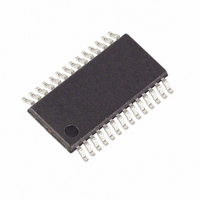
MAXQ3180-RAN+ Maxim Integrated Products, MAXQ3180-RAN+ Datasheet - Page 56

MAXQ3180-RAN+
Manufacturer Part Number
MAXQ3180-RAN+
Description
IC AFE POLYPHASE MULTI 28-TSSOP
Manufacturer
Maxim Integrated Products
Datasheet
1.MAXQ3180-RAN.pdf
(101 pages)
Specifications of MAXQ3180-RAN+
Number Of Channels
8
Power (watts)
35mW
Voltage - Supply, Analog
3.6V
Voltage - Supply, Digital
3.6V
Package / Case
28-TSSOP
For Use With
MAXQ3180-KIT - KIT EV REFRNC DSIGN FOR MAXQ3180
Lead Free Status / RoHS Status
Lead free / RoHS Compliant
Number Of Bits
-
Low-Power, Multifunction, Polyphase AFE
• Power (active, reactive, and apparent) for each
• Energy accumulation (including energy pulse output
• Overvoltage detection
• Overcurrent detection
• Undervoltage detection
On every ADC frame, the input samples are processed
as follows:
• The voltage and current samples are read. The cur-
• Both the current and voltage signals are passed
• The current and voltage signals are now split into
The result is a set of accumulated values that represent
squared voltage, squared current, and real (active) and
reactive (P and Q) energies for both the entire usable
spectrum and as filtered by the peak filter. The real and
Figure 9. Per Sample Operations
56
phase
function)
rent sample is shifted to account for the gain applied
in the PGA. The phase- and gain-corrected samples
are passed to the next stage.
through highpass filters (HPF) specified by the
HPF_C variable.
several components. The first of these components is
squared and accumulated to begin the RMS current
and voltage process. The second is processed and
accumulated to begin the real/reactive power calcu-
lation. And a third is processed through a peak filter
(specified by B0FUND and A1FUND registers) and
then accumulated to provide information for the fun-
damental frequency power calculations.
______________________________________________________________________________________
CURRENT INPUT
VOLTAGE INPUT
Per Sample Operations
GAIN SEL
ADC
ADC
V_GAIN
I_GAIN
HPF
HPF
imaginary components of energy at this point do not yet
represent real and reactive power; to obtain usable
power values further processing is required. Each of
these values is further processed at the end of each
DSP cycle.
At the end of each DSP cycle, accumulated information
is available that is used to calculate all other opera-
tional results in the meter. DSP cycles track the line fre-
quency and have a duration of the number of cycles
specified in the CYCNT register. On each phase, the
time required for CYCNT cycles to complete is calculat-
ed and this value is used to update the duration of one
DSP cycle, specified in the NS register.
NS contains the number of ADC frame periods in a sin-
gle DSP cycle. Because line frequency varies slightly
from cycle to cycle, and because the ADC frame clock
is not synchronized to the line, the value of NS is not an
integer, and varies slightly from DSP cycle to DSP cycle.
Because the value of NS is so critical to accurate calcu-
lation of energy, ensuring that it is correct on every
cycle is essential. There are two ways to manage the
slight variation of NS from cycle to cycle: first, one
could simply replace the old value of NS with the newly
calculated value on each DSP cycle. This means that
NS (and every other value in the meter, since they
depend on NS) would have a significant amount of
uncertainty. A better method is to use each newly cal-
culated value of NS as an input to a filter. The output of
the filter is then the value of NS that is actually used in
calculations. In the MAXQ3180, this filter is controlled
by the AVG_NS register.
X
X
2
2
I
V
2
2
BPF
BPF
E
E
P
Q
Per DSP Cycle Operations
E
E
PF
QF


