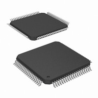
ISL98003INZ-110 Intersil, ISL98003INZ-110 Datasheet - Page 22

ISL98003INZ-110
Manufacturer Part Number
ISL98003INZ-110
Description
IC AFE 3CH 8BIT 110MHZ 80EPTQFP
Manufacturer
Intersil
Datasheet
1.ISL98003CNZ-110.pdf
(31 pages)
Specifications of ISL98003INZ-110
Number Of Bits
8
Number Of Channels
3
Power (watts)
1.1W
Voltage - Supply, Analog
1.8V, 3.3V
Voltage - Supply, Digital
1.65 V ~ 2 V
Package / Case
80-TQFP Exposed Pad, 80-eTQFP, 80-HTQFP, 80-VQFP
Lead Free Status / RoHS Status
Lead free / RoHS Compliant
Available stocks
Company
Part Number
Manufacturer
Quantity
Price
Company:
Part Number:
ISL98003INZ-110
Manufacturer:
GE
Quantity:
340
The offset controls shift the entire RGB input range, changing
the input image brightness. Three separate registers provide
independent control of the R, G, and B channels. Their
nominal setting is 0x8000, which forces the ADC to output
code 0x00 (or 0x80 for the R (Pr) and B (Pb) channels in
YPbPr mode) during the back porch period when ABLC is
enabled.
Functional Description
Inputs
The ISL98003 digitizes analog video inputs in both RGB
and Component (YPbPr) formats, with or without
embedded sync (SOG).
RGB Inputs
For RGB inputs, the black/blank levels are identical and equal
to 0V. The range for each color is typically 0V to 0.7V from
black to white. HSYNC and VSYNC are separate signals.
Component YPbPr Inputs
In addition to RGB and RGB with SOG, the ISL98003 has an
option that is compatible with the component YPbPr video
inputs typically generated by DVD players. While the
ISL98003 digitizes signals in these color spaces, it does not
perform color space conversion; if it digitizes an RGB signal,
it outputs digital RGB, while if it digitizes a YPbPr signal, it
outputs digital YCbCr, also called YUV.
The Luminance (Y) signal is applied to the Green Channel
and is processed in a manner identical to the Green input
with SOG described previously. The color difference signals
Pb and Pr are bipolar and swing both above and below the
black level. When the YPbPr mode is enabled, the black
level output for the color difference channels shifts to a mid
scale value of 0x80. Setting configuration register
0x10[4] = 1 enables the YPbPr signal processing mode of
operation.
SIGNAL
INPUT
Pb
Pr
Y
TABLE 1. YUV MAPPING (4:4:4)
CHANNEL
ISL98003
INPUT
Green
Blue
Red
22
ASSIGNMENT
ISL98003
OUTPUT
Green
Blue
Red
U
Y
V
OUTPUT
SIGNAL
0
0
0
U
Y
V
1
1
1
Y
U
V
2
2
2
Y
V
U
3
3
3
ISL98003
The ISL98003 can optionally decimate the incoming data to
provide a 4:2:2 output stream (configuration register
0x28[0] = 1) as shown in Table 2.
Input Coupling
Inputs can be either AC-coupled (default) or DC-coupled
(see register 0x10[3]). AC coupling is usually preferred since
it allows video signals with substantial DC offsets to be
accurately digitized. The ISL98003 provides a complete
internal DC-restore function, including the DC-restore clamp
(see Figure 1) and programmable clamp timing (registers
0x24, 0x25, and 0x26).
When AC-coupled, the DC-restore clamp is applied every
line, a programmable number of pixels after the trailing edge
of HSYNC. If register 0x60[2] = 0 (the default), the clamp will
not be applied while the DPLL is coasting, preventing any
clamp voltage errors from composite sync edges,
equalization pulses, or Macrovision signals.
After the trailing edge of HSYNC, the DC-restore clamp is
turned on after the number of pixels specified in the
DC-Restore and ABLC Starting Pixel registers (0x24 and
0x25) has been reached. The clamp is applied for the
number of pixels specified by the DC-Restore Clamp Width
Register (0x26). The clamp can be applied to the back porch
of the video, or to the front porch (by increasing the
DC-Restore and ABLC Starting Pixel registers so all the
active video pixels are skipped).
Note: The Tri-level detect for Sync on Green (SOG) utilizes
the digitized data from the selected Green video channel. If
Tri-level Sync is present, the default DC Clamp start position
will clamp at the top of the Tri-level Sync pulse giving a false
negative for Tri-level detect and clamping off the bottom half
of the green video. If you have an indication of active SOG
you must move the clamp start to a value greater than 0x30
to check to see if the Tri-level Sync is present.
If DC-coupled operation is desired, the input to the ADC will
be the difference between the input signal (R
example) and ground.
SIGNAL
INPUT
Pb
Pr
Y
TABLE 2. YUV MAPPING (4:2:2)
CHANNEL
ISL98003
INPUT
Green
Blue
Red
ASSIGNMENT
ISL98003
OUTPUT
Green
Blue
Red
IN
September 12, 2008
1, for
Driven Low
U
Y
OUTPUT
SIGNAL
0
0
Y
V
1
0
Y
U
FN6760.0
2
2
Y
V
3
2


