DS1554-70IND+ Maxim Integrated Products, DS1554-70IND+ Datasheet - Page 3
DS1554-70IND+
Manufacturer Part Number
DS1554-70IND+
Description
IC RTC RAM Y2K 5V 70NS 32-EDIP
Manufacturer
Maxim Integrated Products
Type
Clock/Calendar/NVSRAM/Y2Kr
Datasheet
1.DS1554P-70.pdf
(18 pages)
Specifications of DS1554-70IND+
Memory Size
256K (32K x 8)
Time Format
HH:MM:SS (24 hr)
Date Format
YY-MM-DD-dd
Interface
Parallel
Voltage - Supply
4.5 V ~ 5.5 V
Operating Temperature
-40°C ~ 85°C
Mounting Type
Through Hole
Package / Case
32-DIP Module (600 mil), 32-EDIP
Lead Free Status / RoHS Status
Lead free / RoHS Compliant


DS1554 256k, Nonvolatile, Y2K-Compliant Timekeeping RAM
DESCRIPTION
The DS1554 is a full-function, year 2000-compliant (Y2KC), real-time clock/calendar (RTC) with an
RTC alarm, watchdog timer, power-on reset, battery monitor, and 32k x 8 nonvolatile static RAM. User
access to all registers within the DS1554 is accomplished with a byte-wide interface as shown in Figure 1.
The RTC registers contain century, year, month, date, day, hours, minutes, and seconds data in 24-hour
binary-coded decimal (BCD) format. Corrections for day of month and leap year are made automatically.
The RTC registers are double-buffered into an internal and external set. The user has direct access to the
external set. Clock/calendar updates to the external set of registers can be disabled and enabled to allow
the user to access static data. Assuming the internal oscillator is turned on, the internal set of registers is
continuously updated; this occurs regardless of external registers settings to guarantee that accurate RTC
information is always maintained.
The DS1554 has interrupt (IRQ/FT) and reset (RST) outputs which can be used to control CPU activity.
The IRQ/FT interrupt output can be used to generate an external interrupt when the RTC Register values
match user programmed alarm values. The interrupt is always available while the device is powered from
the system supply and can be programmed to occur when in the battery-backed state to serve as a system
wakeup. Either the IRQ/FT or RST outputs can also be used as a CPU watchdog timer, CPU activity is
monitored and an interrupt or reset output will be activated if the correct activity is not detected within
programmed limits. The DS1554 power-on reset can be used to detect a system power down or failure
and hold the CPU in a safe reset state until normal power returns and stabilizes; the RST output is used
for this function.
The DS1554 also contains its own power-fail circuitry, which automatically deselects the device when the
V
supply enters an out of tolerance condition. This feature provides a high degree of data security
CC
during unpredictable system operation brought on by low V
levels.
CC
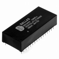
PACKAGES
The DS1554 is available in two packages (32-pin encapsulated DIP and 34-pin PowerCap module). The
32-pin DIP style module integrates the crystal, lithium energy source, and silicon all in one package. The
34-pin PowerCap module board is designed with contacts for connection to a separate PowerCap
(DS9034PCX) that contains the crystal and battery. This design allows the PowerCap to be mounted on
top of the DS1554P after the completion of the surface mount process. Mounting the PowerCap after the
surface mount process prevents damage to the crystal and battery due to the high temperatures required
for solder reflow. The PowerCap is keyed to prevent reverse insertion. The PowerCap Module board and
PowerCap are ordered separately and shipped in separate containers. The part number for the PowerCap
is DS9034PCX.
3 of 18
Related parts for DS1554-70IND+
Image
Part Number
Description
Manufacturer
Datasheet
Request
R

Part Number:
Description:
IC RTC RAM Y2K 5V 70NS 32-EDIP
Manufacturer:
Maxim Integrated Products
Datasheet:
Part Number:
Description:
IC RTC RAM Y2K 5V 70NS 32-EDIP
Manufacturer:
Maxim Integrated Products
Datasheet:
Part Number:
Description:
IC RTC RAM Y2K 5V 70NS 32-EDIP
Manufacturer:
Maxim Integrated Products
Datasheet:

Part Number:
Description:
MAX7528KCWPMaxim Integrated Products [CMOS Dual 8-Bit Buffered Multiplying DACs]
Manufacturer:
Maxim Integrated Products
Datasheet:
Part Number:
Description:
Single +5V, fully integrated, 1.25Gbps laser diode driver.
Manufacturer:
Maxim Integrated Products
Datasheet:
Part Number:
Description:
Single +5V, fully integrated, 155Mbps laser diode driver.
Manufacturer:
Maxim Integrated Products
Datasheet:
Part Number:
Description:
VRD11/VRD10, K8 Rev F 2/3/4-Phase PWM Controllers with Integrated Dual MOSFET Drivers
Manufacturer:
Maxim Integrated Products
Datasheet:
Part Number:
Description:
Highly Integrated Level 2 SMBus Battery Chargers
Manufacturer:
Maxim Integrated Products
Datasheet:
Part Number:
Description:
Current Monitor and Accumulator with Integrated Sense Resistor; ; Temperature Range: -40°C to +85°C
Manufacturer:
Maxim Integrated Products
Part Number:
Description:
TSSOP 14/A°/RS-485 Transceivers with Integrated 100O/120O Termination Resis
Manufacturer:
Maxim Integrated Products
Part Number:
Description:
TSSOP 14/A°/RS-485 Transceivers with Integrated 100O/120O Termination Resis
Manufacturer:
Maxim Integrated Products
Part Number:
Description:
QFN 16/A°/AC-DC and DC-DC Peak-Current-Mode Converters with Integrated Step
Manufacturer:
Maxim Integrated Products
Part Number:
Description:
TDFN/A/65V, 1A, 600KHZ, SYNCHRONOUS STEP-DOWN REGULATOR WITH INTEGRATED SWI
Manufacturer:
Maxim Integrated Products
Part Number:
Description:
Integrated Temperature Controller f
Manufacturer:
Maxim Integrated Products
Part Number:
Description:
SOT23-6/I°/45MHz to 650MHz, Integrated IF VCOs with Differential Output
Manufacturer:
Maxim Integrated Products