ISL12058IRTZ Intersil, ISL12058IRTZ Datasheet - Page 11
ISL12058IRTZ
Manufacturer Part Number
ISL12058IRTZ
Description
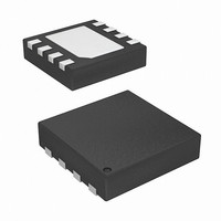
IC RTC/CALENDAR I2C-BUS 8-TDFN
Manufacturer
Intersil
Type
Clock/Calendar/Alarmr
Datasheet
1.ISL12058IBZ-T.pdf
(19 pages)
Specifications of ISL12058IRTZ
Time Format
HH:MM:SS (12/24 hr)
Date Format
YY-MM-DD-dd
Interface
I²C, 2-Wire Serial
Voltage - Supply
1.4 V ~ 3.6 V
Operating Temperature
-40°C ~ 85°C
Mounting Type
Surface Mount
Package / Case
8-TDFN
Lead Free Status / RoHS Status
Lead free / RoHS Compliant
Memory Size
-


FREQUENCY OUT CONTROL BITS (FO <1:0>)
These bits select the output frequency at the IRQ/F
IRQE must be set to “0” for frequency output at the
IRQ/F
ALARM ENABLE BITS (ALM1E, ALM2E)
This bit enables/disables the Alarm1 and Alarm2 function.
When the ALM1E bit is set to “1”, the Alarm1 function is
enabled. When the ALM1E is cleared to “0”, the alarm function
is disabled. ALM1E bit is set to “0” at power-up.
When the ALM2E bit is set to “1”, the Alarm2 function is
enabled. When the ALM2E is cleared to “0”, the alarm function
is disabled. ALM2E bit is set to “0” at power-up.
NOTE: The Alarm1 has hardware function via the IRQ/F
Alarm2 does not have hardware interrupt function.
Alarm1 Registers
Addresses [Address 0Ch to 11h]
The Alarm1 register bytes are set up identical to the RTC
register bytes, except that the MSB of each byte functions as
an enable bit (enable = “1”). These enable bits specify which
alarm registers (seconds, minutes, etc) are used to make the
comparison. Note that there is no alarm byte for year. When
all the enable bits are set to “0” with ALM1E set to “1”, the
Alarm 1 will triggered once a second.
The Alarm1 function works as a comparison between the
Alarm1 registers and the RTC registers. As the RTC
advances, the Alarm1 will be triggered once a match occurs
between the Alarm1 registers and the RTC registers. Any
one Alarm1 register, multiple registers, or all registers can be
enabled for a match.
To clear an Alarm1, the A1F status bit can be set to “0” with a
write or use the ARST bit auto reset function.
A1E
TABLE 4. FUNCTION SELECTION OF IRQ/F
TABLE 5. FREQUENCY SELECTION OF IRQ/F
FO1
1
1
1
1
0
0
OUT
IRQE
pin. Refer to Table 5 for frequency selection.
FO0
0
1
A1E AND IRQE BITS (Continued)
FO1 AND FO0 BITS
1
0
1
0
FREQUENCY,
F
OUT
32768
8192
4096
1
(Hz)
IRQ/F
11
Alarm 1 Interrupt
OUT
F
Free running crystal clock
Free running crystal clock
Free running crystal clock
OUT
FUNCTION
Sync. at RTC write
COMMENT
OUT
OUT
PIN WITH
PIN WITH
OUT
OUT
pin.
pin.
ISL12058
Following is example of Alarm1 Interrupt.
Example – A single alarm will occur on January 1 at
11:30am.
A. Set Alarm1 registers as follows:
TABLE 6. ALARM1 INTERRUPT WITH ENABLE BITS SELECTION
A1M1
0
1
0
0
0
0
0
1
1
1
0
1
0
1
.
.
.
.
.
.
A1M2
0
0
1
0
0
0
0
1
0
1
0
0
1
1
.
.
.
.
.
A1M3
0
0
0
1
0
0
0
0
1
1
0
0
1
1
.
.
.
.
.
.
A1M4
0
0
0
0
1
0
0
0
0
0
1
1
1
1
.
.
.
.
.
.
A1M5
0
0
0
0
0
1
0
0
0
0
1
1
1
1
.
.
.
.
.
.
A1M6
0
0
0
0
0
0
1
0
0
0
1
1
1
1
.
.
.
.
.
.
Minute, and Hour
Date, Month, and
Date, Month, and
Month, and Day
Month, and Day
Match Second,
Match Second,
Match Second,
Match Second
Match Second
Match Second
Every Second
Match MInute,
Match Minute
MInute, Hour,
Match Month
Match Date,
Match Hour
Match Date
Hour, Date,
and Minute
Match Day
ALARM1
Interrupt
and Hour
June 15, 2009
Day
Day
.
.
.
FN6756.0
Related parts for ISL12058IRTZ
Image
Part Number
Description
Manufacturer
Datasheet
Request
R

Part Number:
Description:
Low Cost and Low Power I2C-Bus Real Time Clock/Calendar
Manufacturer:
Intersil Corporation
Datasheet:
Part Number:
Description:
Intersil Corporation [CMOS Serial Controller Interface]
Manufacturer:
Intersil Corporation
Datasheet:
Part Number:
Description:
Manufacturer:
Intersil Corporation
Datasheet:
Part Number:
Description:
357-036-542-201 CARDEDGE 36POS DL .156 BLK LOPRO
Manufacturer:
Intersil Corporation
Datasheet:
Part Number:
Description:
1024-Word x 4-Bit LSI Static RAM
Manufacturer:
Intersil Corporation
Datasheet:
Part Number:
Description:
General Purpose NPN Transistor Arrays FN341.4
Manufacturer:
Intersil Corporation
Datasheet:
Part Number:
Description:
CMOS 16-Bit Microprocessor
Manufacturer:
Intersil Corporation
Datasheet:
Part Number:
Description:
Manufacturer:
Intersil Corporation
Datasheet:
Part Number:
Description:
Manufacturer:
Intersil Corporation
Datasheet:
Part Number:
Description:
Manufacturer:
Intersil Corporation
Datasheet:
Part Number:
Description:
Manufacturer:
Intersil Corporation
Datasheet:
Part Number:
Description:
CMOS 6-Bit Latch and Decoder Memory Interfaces
Manufacturer:
Intersil Corporation
Datasheet:
Part Number:
Description:
CA3046General Purpose NPN Transistor Arrays
Manufacturer:
Intersil Corporation
Datasheet:
Part Number:
Description:
Manufacturer:
Intersil Corporation
Datasheet:
Part Number:
Description:
TR909 DLC/FLC SLIC with Low Power Standby
Manufacturer:
Intersil Corporation
Datasheet: