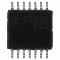
ISL12032IVZ-T Intersil, ISL12032IVZ-T Datasheet - Page 8

ISL12032IVZ-T
Manufacturer Part Number
ISL12032IVZ-T
Description
IC RTC LP BATT BACK SRAM 14TSSOP
Manufacturer
Intersil
Type
Clock/Calendar/NVSRAMr
Datasheet
1.ISL12032IVZ-T.pdf
(26 pages)
Specifications of ISL12032IVZ-T
Memory Size
1K (128 x 8)
Time Format
HH:MM:SS:hh (12/24 hr)
Date Format
YY-MM-DD-dd
Interface
I²C, 2-Wire Serial
Voltage - Supply
2.7 V ~ 5.5 V
Operating Temperature
-40°C ~ 85°C
Mounting Type
Surface Mount
Package / Case
14-TSSOP
Lead Free Status / RoHS Status
Lead free / RoHS Compliant
Other names
ISL12032IVZ-TTR
Available stocks
Company
Part Number
Manufacturer
Quantity
Price
Company:
Part Number:
ISL12032IVZ-T
Manufacturer:
Intersil
Quantity:
11 856
General Description
The ISL12032 device is a low power real time clock with
50/60 AC input for timing synchronization. It also has an
oscillator utilizing an external crystal for timing back-up,
clock/calendar registers, intelligent battery back-up
switching, battery voltage monitor, brownout indicator,
integrated trickle charger for super capacitor, single periodic
or polled alarms, POR supervisory function, and up to 4
Event Detect with time stamp. There are 128 bytes of
battery-backed user SRAM.
The oscillator uses a 50/60 cycle sine wave input, backed by
an external, low-cost, 32.768kHz crystal. The real time clock
tracks time with separate registers for hours, minutes, and
seconds. The calendar registers contain the date, month,
year, and day of the week. The calendar is accurate through
year 2100, with automatic leap year correction and auto
daylight savings correction.
The ISL12032’s alarm can be set to any clock/calendar
value for a match. Each alarm’s status is available by
checking the Status Register. The device also can be
configured to provide a hardware interrupt via the IRQ pin.
There is a repeat mode for the alarms allowing a periodic
interrupt every minute, every hour, every day, etc.
The device also offers a backup power input pin. This VBAT
pin allows the device to be backed up by battery or Super
Capacitor with automatic switchover from V
ISL12032 devices are specified for V
the clock/calendar portion of the device remains fully
operational in battery backup mode down to 1.8V (Standby
Mode). The VBAT level is monitored and warnings are
reported against preselected levels. The first report is
registered when the VBAT level falls below 85% of nominal
level, the second level is set for 75% of nominal level.
Battery levels are stored in the PWRBAT registers.
The ISL12032 offers a “Brownout” alarm once the V
below a pre-selected trip level. In the ISL12032, this allows
the system microcontroller to save vital information to
memory before complete power loss. There are six V
levels for the brownout alarm.
The event detection function accepts a normally low logic
input, and when triggered will store the time/date information
for the event. The first event is stored in the memory until
reset; subsequent events are stored on-chip memory and
the last 3 events are retained and accessible by performing
an indexed register read.
8
DD
= 2.7V to 5.5V and
DD
to VBAT. The
DD
DD
falls
trip
ISL12032
Pin Descriptions
X1, X2
The X1 and X2 pins are the input and output, respectively, of
an inverting amplifier. An external 32.768kHz quartz crystal
is used with the device to supply a backup timebase for the
real time clock if there is no AC input. The device also can
be driven directly from a 32.768kHz source at pin X1, in
which case, pin X2 should be left unconnected. No external
load capacitors are needed for the X1 and X2 pins.
VBAT (Battery Input)
This input provides a backup supply voltage to the device.
VBAT supplies power to the device in the event that the VDD
supply fails. This pin can be connected to a battery, a Super
Capacitor or tied to ground if not used.
AC (AC Input)
The AC input is the main clock input for the real time clock. It
can be either 50Hz or 60Hz, sine wave. The preferred
amplitude is 2.5V
acceptable. An AC coupled (series capacitor) sine wave
clock waveform is desired as the AC clock input provides DC
biasing.
LV (Low Voltage)
This pin indicates the VDD supply is below the programmed
level. This signal notifies a host processor that the main
supply is low and requests action. It is an open drain active
LOW output.
EVIN (Event Input)
The EVIN pin input detects an externally monitored event.
When a HIGH signal is present at the EVIN pin, an “event” is
detected.This input may be used for various monitoring
functions, such as the opening of a detection switch on a
chassis or door. The event detection circuit can be user
enabled or disabled (see EVIN bit) and provides the option
to be operational in battery backup modes (see EVATB bit).
When the event detection is disabled, the EVIN pin is gated
OFF. See “Functional Pin Descriptions” on page 3 for more
details.
EVDET (Event Detect Output)
The EVDET is an open drain output, which will go low when
an event is detected at the EVIN pin. If the event detection
function is enabled, the EVDET output will go LOW and stay
there until the EVT bit is cleared.
FIGURE 2. RECOMMENDED CRYSTAL CONNECTION
P-P
, although amplitudes >0.25V
X1
X2
DD
April 16, 2009
are
FN6618.2


