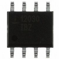
ISL12030IBZ-T Intersil, ISL12030IBZ-T Datasheet

ISL12030IBZ-T
Specifications of ISL12030IBZ-T
Available stocks
Related parts for ISL12030IBZ-T
ISL12030IBZ-T Summary of contents
Page 1
... PART NUMBER (Note) PART MARKING ISL12030IBZ* 12030 IBZ *Add “-T” suffix for tape and reel. Please refer to TB347 for details on reel specifications. NOTE: These Intersil Pb-free plastic packaged products employ special Pb-free material sets; molding compounds/die attach materials and 100% matte tin plate PLUS ANNEAL - e3 termination finish, which is RoHS compliant and compatible with both SnPb and Pb-free soldering operations ...
Page 2
Block Diagram SDA SDA BUFFER SCL SCL BUFFER V INTERNAL DD SUPPLY AC INPUT BUFFER AC GND Functional Pin Descriptions PIN NUMBER SYMBOL 2 GND Ground Input. The AC input pin accepts either 50Hz of 60Hz AC ...
Page 3
... SDA Output Buffer LOW Voltage, OL Sinking 3mA 3 ISL12030 Thermal Information Thermal Resistance (Typical, Note SOIC . . . . . . . . . . . . . . . . . . . . . . . . . . . . . . . . Storage Temperature . . . . . . . . . . . . . . . . . . . . . . . .-65°C to +150°C Pb-free reflow profile . . . . . . . . . . . . . . . . . . . . . . . . . .see link below http://www.intersil.com/pbfree/Pb-FreeReflow.asp = 2.7V to 5.5V -40°C to +85°C, unless otherwise stated MIN CONDITIONS (Note 8) 2 5V, SCL, SDA = V ...
Page 4
I C Interface Specifications Specifications apply for: V unless otherwise stated. (Continued) SYMBOL PARAMETER C SDA and SCL Pin Capacitance PIN f SCL Frequency SCL t Pulse Width Suppression Time at IN SDA and SCL Inputs t SCL Falling ...
Page 5
I C Interface Specifications Specifications apply for: V unless otherwise stated. (Continued) SYMBOL PARAMETER R SDA and SCL Bus Pull-up Resistor PU Off-chip NOTES: 2. IRQ Inactive. 3. Specified at T =+25° 400kHz. SCL 5. ...
Page 6
General Description The ISL12030 device is a low power real time clock with 50/60 AC input for timing synchronization, clock/calendar registers, single periodic or polled alarms. There are 128 bytes of user SRAM. The oscillator uses a 50/60 cycle sine ...
Page 7
I C serial bus protocols using a bi-directional data signal (SDA) and a clock signal (SCL). Register Descriptions The registers are accessible following an I “1101 111x” and reads or writes to addresses [00h:47h]. The defined addresses and ...
Page 8
TABLE 1. REGISTER MEMORY MAP (X indicates writes to these bits have no effect on the device) (Continued) REG ADDR SECTION NAME 7 23h SCA1 ESCA1 24h MNA1 EMNA1 25h HRA1 EHRA1 Alarm1 26h DTA1 EDTA1 27h MOA1 EMOA1 28h ...
Page 9
Real Time Clock Registers Addresses [00h to 07h] RTC REGISTERS (SC, MN, HR, DT, MO, YR, DW, SS) These registers depict BCD representations of the time. As such, SC (Seconds) and MN (Minutes) range from 0 to 59, HR (Hour) ...
Page 10
IRQ pin will be set LOW until both the ALM0/ALM1 status bits are cleared to “0”. ALARM 1 (ALE 1) This bit enables the Alarm1 function. When ALE1 ...
Page 11
ADDRESS FUNCTION 7 15h Month Forward DSTE 16h Day Forward 0 17h Date Forward 0 18h Hour Forward HrFdMIL ADDRESS NAME 7 19h Month Reverse 0 1Ah Day Reverse 0 1Bh Date Reverse 0 1Ch Hour Reverse HrRvMIL ALARM Registers ...
Page 12
Example 2 • Pulsed interrupt once per minute (IM = ”1”) • Interrupts at one minute intervals when the seconds register seconds. • Set Alarm registers as follows: BIT ALARM REGISTER ...
Page 13
SCL SDA START FIGURE 3. VALID DATA CHANGES, START AND STOP CONDITIONS SCL FROM MASTER SDA OUTPUT FROM TRANSMITTER SDA OUTPUT FROM RECEIVER START FIGURE 4. ACKNOWLEDGE RESPONSE FROM RECEIVER SIGNALS FROM THE MASTER SIGNAL AT SDA SIGNALS FROM THE ...
Page 14
FIGURE 6. SLAVE ADDRESS, WORD ADDRESS AND DATA BYTES Write Operation A Write operation requires a START condition, ...
Page 15
Application Section AC Input Circuits The AC input ideally will have a 2.5V P-P input, so this is the target for any signal conditioning circuitry for the 50/60Hz waveform. Note that the peak-to-peak amplitude can range from ...
Page 16
FIGURE 10. ADDING A SUPER CAPACITOR TO PROVIDE BACKUP FOR SRAM 16 ISL12030 1N4148 REGULATED SUPPLY VOLTAGE SUPER + CAPACITOR, >0.22F ISL12030 V DD FN6617.1 January 15, 2008 ...
Page 17
... Accordingly, the reader is cautioned to verify that data sheets are current before placing orders. Information furnished by Intersil is believed to be accurate and reliable. However, no responsibility is assumed by Intersil or its subsidiaries for its use; nor for any infringements of patents or other rights of third parties which may result from its use ...


