M48T58-70PC1 STMicroelectronics, M48T58-70PC1 Datasheet - Page 16
M48T58-70PC1
Manufacturer Part Number
M48T58-70PC1
Description
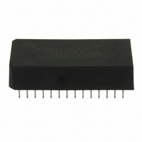
IC TIMEKPR NVRAM 64KBIT 5V 28-DI
Manufacturer
STMicroelectronics
Series
Timekeeper®r
Type
Clock/Calendar/NVSRAMr
Datasheet
1.M48T58-70PC1.pdf
(33 pages)
Specifications of M48T58-70PC1
Memory Size
64K (8K x 8)
Time Format
HH:MM:SS (24 hr)
Date Format
YY-MM-DD-dd
Interface
Parallel
Voltage - Supply
4.75 V ~ 5.5 V
Operating Temperature
0°C ~ 70°C
Mounting Type
Through Hole
Package / Case
28-DIP Module (600 mil), 28-EDIP
Function
Clock/Calendar/NV Timekeeping RAM/Battery Backup
Rtc Memory Size
8192 Byte
Supply Voltage (max)
5.5 V
Supply Voltage (min)
4.75 V
Maximum Operating Temperature
+ 70 C
Minimum Operating Temperature
0 C
Mounting Style
Through Hole
Rtc Bus Interface
Parallel
Clock Format
HH
Clock Ic Type
Timekeeper
Memory Configuration
8K X 8
Supply Voltage Range
4.75V To 5.5V
Digital Ic Case Style
DIP
No. Of Pins
28
Rohs Compliant
Yes
Lead Free Status / RoHS Status
Lead free / RoHS Compliant
Other names
497-2857-5
Available stocks
Company
Part Number
Manufacturer
Quantity
Price
Company:

Part Number:
M48T58-70PC1
Manufacturer:
NS
Quantity:
290
Company:
Part Number:
M48T58-70PC1
Manufacturer:
XILINX
Quantity:
86
Part Number:
M48T58-70PC1
Manufacturer:
ST
Quantity:
20 000


Clock operations
Note:
6.4
16/33
Table 5.
Keys:
When CEB is set to '1,' CB will toggle from '0' to '1' or from '1' to '0' at the turn of the century
(dependent upon the initial value set).
When CEB is set to '0,' CB will not toggle. The WRITE bit does not need to be set to write to
CEB.
Calibrating the clock
The M48T58/Y is driven by a quartz-controlled oscillator with a nominal frequency of 32,768
Hz. The devices are tested not to exceed 35 ppm (parts per million) oscillator frequency
error at 25°C, which equates to about ±1.53 minutes per month. With the calibration bits
properly set, the accuracy of each M48T58/Y improves to better than +1/–2 ppm at 25°C.
The oscillation rate of any crystal changes with temperature (see
Most clock chips compensate for crystal frequency and temperature shift error with
cumbersome “trim” capacitors. The M48T58/Y design, however, employs periodic counter
correction. The calibration circuit adds or subtracts counts from the oscillator divider circuit
at the divide by 256 stage, as shown in
are blanked (subtracted, negative calibration) or split (added, positive calibration) depends
upon the value loaded into the five calibration bits found in the control register. Adding
counts speeds the clock up, subtracting counts slows the clock down.
The calibration byte occupies the five lower order bits (D4-D0) in the control register 1FF8h.
These bits can be set to represent any value between 0 and 31 in binary form. Bit D5 is the
Address
1FFDh
1FFCh
1FFFh
1FFEh
1FFBh
1FFAh
1FF9h
1FF8h
S = SIGN bit
FT = FREQUENCY TEST bit
R = READ bit
W = WRITE bit
ST = STOP bit
0 = Must be set to '0'
BLE = Battery low enable bit
BL = Battery low bit (read only)
CEB = Century enable bit
CB = Century bit
BLE
ST
D7
Register map
W
0
0
0
0
D6
BL
FT
R
10 Years
0
0
10 seconds
10 minutes
CEB
D5
S
0
10 hours
10 date
Doc ID 2412 Rev 7
10 M
CB
D4
Data
Figure 9 on page
D3
0
Calibration
D2
Seconds
Minutes
Month
Hours
Date
Year
Day
D1
18. The number of times pulses
D0
Figure 8 on page
Century/day
Seconds
Minutes
Control
Month
Hours
Date
Year
Function/range
M48T58, M48T58Y
BCD format
0-1/1-7
00-99
01-12
01-31
00-23
00-59
00-59
18).
Related parts for M48T58-70PC1
Image
Part Number
Description
Manufacturer
Datasheet
Request
R

Part Number:
Description:
5.0v, 64 Kbit 8 Kb X 8 Timekeeper Sram
Manufacturer:
STMicroelectronics
Datasheet:
Part Number:
Description:
STMicroelectronics [RIPPLE-CARRY BINARY COUNTER/DIVIDERS]
Manufacturer:
STMicroelectronics
Datasheet:
Part Number:
Description:
STMicroelectronics [LIQUID-CRYSTAL DISPLAY DRIVERS]
Manufacturer:
STMicroelectronics
Datasheet:

Part Number:
Description:
BOARD EVAL FOR MEMS SENSORS
Manufacturer:
STMicroelectronics
Datasheet:
Part Number:
Description:
NPN TRANSISTOR POWER MODULE
Manufacturer:
STMicroelectronics
Datasheet:
Part Number:
Description:
TURBOSWITCH ULTRA-FAST HIGH VOLTAGE DIODE
Manufacturer:
STMicroelectronics
Datasheet:
Part Number:
Description:
Manufacturer:
STMicroelectronics
Datasheet:
Part Number:
Description:
DIODE / SCR MODULE
Manufacturer:
STMicroelectronics
Datasheet:
Part Number:
Description:
DIODE / SCR MODULE
Manufacturer:
STMicroelectronics
Datasheet:
Part Number:
Description:
Search -----> STE16N100
Manufacturer:
STMicroelectronics
Datasheet:
Part Number:
Description:
Search ---> STE53NA50
Manufacturer:
STMicroelectronics
Datasheet:
Part Number:
Description:
NPN Transistor Power Module
Manufacturer:
STMicroelectronics
Datasheet: