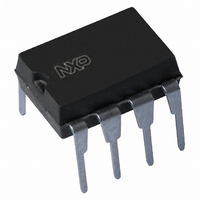
PCF8583P/F5,112 NXP Semiconductors, PCF8583P/F5,112 Datasheet - Page 14

PCF8583P/F5,112
Manufacturer Part Number
PCF8583P/F5,112
Description
IC CLK/CALENDAR 240X8 RAM 8-DIP
Manufacturer
NXP Semiconductors
Type
Clock/Calendar/NVSRAMr
Datasheet
1.PCF8583T5518.pdf
(37 pages)
Specifications of PCF8583P/F5,112
Package / Case
8-DIP (0.300", 7.62mm)
Memory Size
240B
Time Format
HH:MM:SS (12/24 hr)
Date Format
YY-MM-DD
Interface
I²C, 2-Wire Serial
Voltage - Supply
1 V ~ 6 V
Operating Temperature
-40°C ~ 85°C
Mounting Type
Through Hole
Mounting Style
Through Hole
Lead Free Status / RoHS Status
Lead free / RoHS Compliant
Lead Free Status / RoHS Status
Lead free / RoHS Compliant, Lead free / RoHS Compliant
Other names
568-1084-5
935261345112
PCF8583PN
935261345112
PCF8583PN
Available stocks
Company
Part Number
Manufacturer
Quantity
Price
Company:
Part Number:
PCF8583P/F5,112
Manufacturer:
LTC
Quantity:
147
NXP Semiconductors
PCF8583
Product data sheet
7.11 Initialization
In the 50 Hz clock mode or event-counter mode the oscillator is disabled and the oscillator
input is switched to a high-impedance state. This allows the user to feed the 50 Hz
reference frequency or an external high speed event signal into the input OSCI.
When power-on occurs the I
counters are reset. The device starts time-keeping in the 32.768 kHz clock mode with the
24 hour format on the first of January at 0.00.00:00. A 1 Hz square wave with 50 % duty
cycle appears at the interrupt output pin (starts HIGH).
The stop counting flag of the control and status register must be set before loading the
actual time into the counters. Loading of illegal states leads to a temporary clock
malfunction.
All information provided in this document is subject to legal disclaimers.
Rev. 06 — 6 October 2010
2
C-bus interface, the control and status register and all clock
Clock and calendar with 240 x 8-bit RAM
PCF8583
© NXP B.V. 2010. All rights reserved.
14 of 37


