NBXDBA012LN1TAG ON Semiconductor, NBXDBA012LN1TAG Datasheet
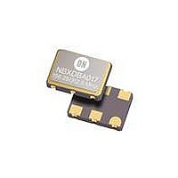
IC CLK OSC 106.25/212.5MHZ 6CLCC

NBXDBA012LN1TAG

Manufacturer Part Number
NBXDBA012LN1TAG
Description
IC CLK OSC 106.25/212.5MHZ 6CLCC
Manufacturer
ON Semiconductor
Type
Clock Oscillatorr
Series
NBXr
Datasheet

Specifications of NBXDBA012LN1TAG

Package / Case
6-CLCC
Voltage - Supply
3 V ~ 3.6 V
Frequency
106.25MHz/212.5MHz
Operating Temperature
-40°C ~ 85°C
Count
*
Frequency Stability
50 PPM
Termination Style
SMD/SMT
Supply Voltage
3.3 Volts
Supply Voltage (min)
2.97 Volts
Supply Voltage (max)
3.63 Volts
Dimensions
5 mm W x 7 mm L x 1.8 mm H
Minimum Operating Temperature
- 40 C
Maximum Operating Temperature
+ 85 C
Duty Cycle (max)
52 %
Mounting Style
SMD/SMT
Product
XO
Height
1.8 mm
Lead Free Status / RoHS Status
Lead free / RoHS Compliant

Available stocks

Company
Part Number
Manufacturer
Quantity
Price
Part Number:
NBXDBA012LN1TAG
Manufacturer:
ON Semiconductor
Quantity:
205
Part Number:
NBXDBA012LN1TAG
Manufacturer:
ON/安森美
Quantity:
20 000
NBXDBA012
3.3 V, 106.25 MHz /
212.5 MHz LVPECL Clock
Oscillator
designed to meet today’s requirements for 3.3 V LVPECL clock
generation applications. The device uses a high Q fundamental crystal
and Phase Lock Loop (PLL) multiplier to provide selectable 106.25
MHz or 212.5 MHz, ultra low jitter and phase noise LVPECL
differential output. This device is a member of ON Semiconductor’s
PureEdget clock family that provides accurate and precision clock
solutions.
and reel in quantities of 1,000.
Features
Applications
© Semiconductor Components Industries, LLC, 2009
October, 2009 − Rev. 5
The NBXDBA012 dual frequency crystal oscillator (XO) is
Available in 5 mm x 7 mm SMD (CLCC) package on 16 mm tape
LVPECL Differential Output
Uses High Q Fundamental Mode Crystal and PLL Multiplier
Ultra Low Jitter and Phase Noise − 0.4 ps (12 kHz − 20 MHz)
Selectable Output Frequency − 106.25 MHz (default)/ 212.5 MHz
Total Frequency Stability − ±50 PPM
Hermetically Sealed Ceramic SMD Package
RoHS Compliant
Operating Range 3.3 V ±10%
This is a Pb−Free Device
1X and 2X Fiber Channel
Host Bus Adapter
Crystal
V
OE
DD
1
6
Figure 1. Simplified Logic Diagram
Multiplier
Clock
FSEL
PLL
2
CLK CLK
GND
5
3
4
1
NBXDBA012LN1TAG CLCC−6
NBXDBA012LNHTAG CLCC−6
†For information on tape and reel specifications,
including part orientation and tape sizes, please
refer to our Tape and Reel Packaging Specification
Brochure, BRD8011/D.
CASE 848AB
6 PIN CLCC
LN SUFFIX
NBXDBA012 = NBXDBA012 (±50 PPM)
106.25/212.5 = Output Frequency (MHz)
AA
WL
YY
WW
G
Device
ORDERING INFORMATION
http://onsemi.com
= Assembly Location
= Wafer Lot
= Year
= Work Week
= Pb−Free Package
(Pb−Free)
(Pb−Free)
Package
MARKING DIAGRAM
Publication Order Number:
AAWLYYWWG
NBXDBA012
106.25/212.5
1000/Tape & Reel
100/Tape & Reel
NBXDBA012/D
Shipping

Related parts for NBXDBA012LN1TAG

NBXDBA012LN1TAG Summary of contents

Page 1

... NBXDBA012 = NBXDBA012 (±50 PPM) 106.25/212.5 = Output Frequency (MHz ORDERING INFORMATION Device NBXDBA012LN1TAG CLCC−6 NBXDBA012LNHTAG CLCC−6 †For information on tape and reel specifications, including part orientation and tape sizes, please CLK CLK refer to our Tape and Reel Packaging Specification 5 4 Brochure, BRD8011/D. ...

Page 2

Table 1. PIN DESCRIPTION Pin No. Symbol I LVTTL/LVCMOS Control Input 2 FSEL LVTTL/LVCMOS Control Input 3 GND Power Supply 4 CLK LVPECL Output 5 CLK LVPECL Output 6 V Power Supply DD Table 2. OUTPUT ENABLE TRI−STATE ...

Page 3

Table 6. DC CHARACTERISTICS (V Symbol Characteristic I Power Supply Current (Note and FSEL Input HIGH Voltage and FSEL Input LOW Voltage IL I Input HIGH Current IH I Input LOW Current IL ...

Page 4

Table 8. RELIABILITY COMPLIANCE Parameter Á Á Á Á Á Á Á Á Á Á Á Shock Á Á Á Á Á Á Á Á Á Á Á Á Á Á Á Á Á Á Á Á Á Á Solderability ...

Page 5

NBXDBA012 CLK o Driver Device CLK Figure 7. Typical Termination for Output Driver and Device Evaluation (See Application Note AND8020/D − Termination of ECL Logic Devices.) temp. 260°C 20 − 40 ...

Page 6

... L 6X 2.54 PITCH *For additional information on our Pb−Free strategy and soldering details, please download the ON Semiconductor Soldering and Mounting Techniques Reference Manual, SOLDERRM/D. N. American Technical Support: 800−282−9855 Toll Free USA/Canada Europe, Middle East and Africa Technical Support: Phone: 421 33 790 2910 Japan Customer Focus Center Phone: 81− ...

Related keywords