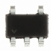
LTC6900CS5#TRMPBF Linear Technology, LTC6900CS5#TRMPBF Datasheet - Page 3

LTC6900CS5#TRMPBF
Manufacturer Part Number
LTC6900CS5#TRMPBF
Description
IC OSC PREC 1KHZ-20MHZ TSOT23-5
Manufacturer
Linear Technology
Type
Oscillator, Siliconr
Datasheet
1.LTC6900CS5TRMPBF.pdf
(12 pages)
Specifications of LTC6900CS5#TRMPBF
Frequency
20MHz
Voltage - Supply
2.7 V ~ 5.5 V
Current - Supply
920µA
Operating Temperature
-40°C ~ 85°C
Package / Case
TSOT-23-5, TSOT-5, TSOP-5
Lead Free Status / RoHS Status
Lead free / RoHS Compliant
Count
-
Other names
LTC6900CS5#TRMPBFTR
Available stocks
Company
Part Number
Manufacturer
Quantity
Price
ELECTRICAL CHARACTERISTICS
temperature range, otherwise specifi cations are at T
All voltages are with respect to GND.
Note 1: Stresses beyond those listed under Absolute Maximum Ratings
may cause permanent damage to the device. Exposure to any Absolute
Maximum Rating condition for extended periods may affect device
reliability and lifetime.
Note 2: Frequencies near 100kHz and 1MHz may be generated using two
different values of R
paragraph in the Applications Information section). For these frequencies,
the error is specifi ed under the following assumption: 20k < R
Note 3: Frequency accuracy is defi ned as the deviation from the
f
Note 4: Jitter is the ratio of the peak-to-peak distribution of the period to
the mean of the period. This specifi cation is based on characterization and
is not 100% tested. Also, see the Peak-to-Peak Jitter vs Output Frequency
curve in the Typical Performance Characteristics section.
SYMBOL
V
I
V
V
I
V
V
t
t
OSC
S
DIV
r
f
+
IH
IL
OH
OL
equation.
PARAMETER
Operating Supply Range
Power Supply Current
High Level DIV Input Voltage
Low Level DIV Input Voltage
DIV Input Current (Note 5)
High Level Output Voltage (Note 5)
Low Level Output Voltage (Note 5)
OUT Rise Time
(Note 6)
OUT Fall Time
(Note 6)
SET
(see the Selecting the Divider Setting Resistor
CONDITIONS
R
f
R
f
Pin 4 = V
Pin 4 = 0V
V
V
V
V
V
V
V
V
OSC
OSC
SET
SET
+
+
+
+
+
+
+
+
= 5V
= 3V
= 5V
= 3V
= 5V
= 3V
= 5V
= 3V
= 5kHz
= 10MHz
= 400k, Pin 4 = V
= 20k, Pin 4 = 0V, R
A
SET
= 25°C. V
+
≤ 200k.
The
l
+
I
I
I
I
I
I
I
I
Pin 4 = V
Pin 4 = 0V, R
Pin 4 = V
Pin 4 = 0V, R
Pin 4 = V
Pin 4 = 0V, R
Pin 4 = V
Pin 4 = 0V, R
= 2.7V to 5.5V, R
denotes the specifi cations which apply over the full operating
OH
OH
OH
OH
OL
OL
OL
OL
+
, R
L
= 1mA
= 4mA
= 1mA
= 4mA
= – 1mA
= –4mA
= – 1mA
= –4mA
L
= ∞
Note 5: To conform with the Logic IC Standard convention, current out of
a pin is arbitrarily given as a negative value.
Note 6: Output rise and fall times are measured between the 10% and 90%
power supply levels. These specifi cations are based on characterization.
Note 7: Guaranteed by 5V test.
Note 8: The LTC6900C is guaranteed to meet specifi ed performance from
0°C to 70°C. The LTC6900C is designed, characterized and expected to
meet specifi ed performance from – 40°C to 85°C but is not tested or
QA sampled at these temperatures. The LTC6900I is guaranteed to meet
specifi ed performance from –40°C to 85°C.
= ∞
+
+
+
+
or Floating, R
or Floating, R
or Floating, R
or Floating, R
L
L
L
L
V
V
V
V
V
V
= ∞
= ∞
= ∞
= ∞
+
+
+
+
+
+
= 5V
= 3V
= 3V
= 5V
= 5V
= 5V
L
= 5k, C
L
L
L
L
= ∞
= ∞
= ∞
= ∞
L
= 5pF , Pin 4 = V
●
●
●
●
●
●
●
●
●
●
●
●
●
●
●
●
●
V
+
MIN
2.7
4.8
4.5
2.7
2.2
– 4
– 0.4
+
unless otherwise noted.
0.32
0.29
0.92
0.68
4.95
0.05
TYP
4.8
2.9
2.6
0.2
0.1
0.4
–2
14
19
11
13
19
10
2
7
6
LTC6900
MAX
0.42
0.38
1.20
0.86
0.15
5.5
0.5
0.4
0.3
0.7
4
UNITS
6900fa
3
mA
mA
mA
mA
μA
μA
ns
ns
ns
ns
ns
ns
ns
ns
V
V
V
V
V
V
V
V
V
V
V


