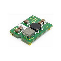
F4804A POWER ONE, F4804A Datasheet - Page 4

F4804A
Manufacturer Part Number
F4804A
Description
DC-DC CONV INP FILTER 4A SMD
Manufacturer
POWER ONE
Series
Fr
Datasheet
1.F4804A.pdf
(41 pages)
Specifications of F4804A
Filter Type
Power Line
Voltage - Rated
80V
Current
4A
Mounting Type
Surface Mount
Termination Style
Surface Mount (SMD,SMT)
Operating Temperature Min Deg. C
-40C
Operating Temperature Max Deg. C
85C
Rad Hardened
No
Input Voltage Range
0 V to 80 V
Input Voltage (nominal)
48 V
Package / Case Size
21.59 mm x 19.05 mm x 6.78 mm
Lead Free Status / RoHS Status
Lead free / RoHS Compliant
Inductance
-
Lead Free Status / Rohs Status
Lead free / RoHS Compliant
Other names
Q4089730
Available stocks
Company
Part Number
Manufacturer
Quantity
Price
Part Number:
F4804A-R
Manufacturer:
PULSE
Quantity:
20 000
Company:
Part Number:
F4804A-RG
Manufacturer:
Bel
Quantity:
131
Part Number:
F4804A-RG
Manufacturer:
PULSE
Quantity:
20 000
The F4804A filter contains input and output
capacitors, plus differential and common mode
inductors. The separate differential inductor, L2,
allows a differential attenuation of 55 dB, a value
substantially
available off-the-shelf filters (typically 25-30 dB).
Absolute maximum voltage and maximum operating
voltage in Electrical Specifications Table are for the
filter itself; check maximum rating for corresponding
dc-dc converters. Filter will not be damaged by
reversed input voltage, or by applying voltage to the
output pins.
Differential attenuation plot in the frequency range of
50 kHz-100 MHz is shown in Fig. 2, and can be seen
to be flat (around 55-60 dB) from 0.5 MHz to
50 MHz.
Fig. 2: Differential mode attenuation, 0.05-100 MHz. Source
and load resistances are 50 Ω. Vertical scale: 20 dB/div, with
zero level marked by arrow. No load @ 25 ºC.
MCD10059 Rev. 1.1, 21-Jan-10
Vin-
Vin+
higher
Fig. 1: Schematic diagram.
2 F
C1
2 x 30 H
L1-1
L1-2
in
comparison
1 F
C2
4.7 H
L2
2 F
C3
with
Vout+
Vout-
F & FC Series DC-DC Converter Input Filters
other
Page 4 of 41
Fig. 3 and Fig. 4 show Common mode attenuation with
50 Ω source and load. The attenuation depends on the
value of external Y-capacitors, connected between input
pins and frame or a reference ground.
F4804A, 0-80V, 4 Amps, SMT Mount
Fig. 3: Common Mode attenuation, 0.05-100 MHz. Source and
load resistances are 50 Ω. Two 0.1 µF Y-caps to common
line. Vertical scale: 20 dB/div, with zero dB level marked by
arrow.
Fig. 4: Common Mode attenuation, 0.05-100 MHz. Source and
load resistances are 50 Ω. Two 0.47 µF Y-caps to common
line. Vertical scale: 20 dB/div, with zero dB level marked by
arrow.
www.power-one.com


