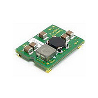
F4804A POWER ONE, F4804A Datasheet - Page 10

F4804A
Manufacturer Part Number
F4804A
Description
DC-DC CONV INP FILTER 4A SMD
Manufacturer
POWER ONE
Series
Fr
Datasheet
1.F4804A.pdf
(41 pages)
Specifications of F4804A
Filter Type
Power Line
Voltage - Rated
80V
Current
4A
Mounting Type
Surface Mount
Termination Style
Surface Mount (SMD,SMT)
Operating Temperature Min Deg. C
-40C
Operating Temperature Max Deg. C
85C
Rad Hardened
No
Input Voltage Range
0 V to 80 V
Input Voltage (nominal)
48 V
Package / Case Size
21.59 mm x 19.05 mm x 6.78 mm
Lead Free Status / RoHS Status
Lead free / RoHS Compliant
Inductance
-
Lead Free Status / Rohs Status
Lead free / RoHS Compliant
Other names
Q4089730
Available stocks
Company
Part Number
Manufacturer
Quantity
Price
Part Number:
F4804A-R
Manufacturer:
PULSE
Quantity:
20 000
Company:
Part Number:
F4804A-RG
Manufacturer:
Bel
Quantity:
131
Part Number:
F4804A-RG
Manufacturer:
PULSE
Quantity:
20 000
The F4810 and F2410 filters contain input and output
capacitors, plus differential and common mode
inductors. Shown in Fig. 1, the schematic diagrams
of both filters are similar, the only difference are
changes in C1, C2 capacitor values. The separate
differential inductor, L2, allows a 50 Ω differential
attenuation of 60 dB across the stated frequency
range, a value substantially higher in comparison
with other available off-the-shelf filters (typically
25-30 dB).
The F4810 can be used in 24 V or 48 V systems
without any limitations; however, in 24 V systems the
F2410 differential attenuation is better. At low
frequencies around 100-200 kHz the difference is
20dB, but at high frequencies the plots are close to
identical.
Absolute maximum voltage and maximum operating
voltage in Electrical Specifications Table are for the
filter itself; check maximum rating for corresponding
dc-dc converters. The filter will not be damaged by
reversed input voltage, or by applying voltage to the
output pins.
Fig. 1: Schematic diagram for F4810, F2410. The Capacitor
values shown are for F4810; for F2410 C1=10 μF; C2=13 μF.
Fig. 2: F4810 - Differential mode attenuation, 0.2-100 MHz.
Source and load resistances are 50 Ω. Vertical scale: 10
dB/div, with zero level marked by arrow. No load, 25 ºC.
MCD10059 Rev. 1.1, 21-Jan-10
V
V
IN-
IN+
C1
3 F
L1-2
L1-1
49.9
R1
4.2 H
L2
F2410 & F4810, 0-45V/0-80V, 10 Amps, SMT Mount
C2
4 F
V
V
OUT+
OUT-
F & FC Series DC-DC Converter Input Filters
Page 10 of 41
Fig. 3: F2410 - Differential mode attenuation, 0.2-100 MHz.
Source and load resistance 50 Ω. Vertical scale: 10 dB/div,
with zero level marked by arrow. No load, 25 ºC.
Differential attenuation plots for the F4810 and
F2410 filters in the extended frequency range of
20 kHz-100 MHz are shown in Fig. 2 and Fig. 3,
respectively, and can be seen to be flat (around
55-60 dB) from 0.35 MHz to 40 MHz.
Fig. 4 shows Common mode attenuation with 50 Ω
source and load. The attenuation is the same for
both filters, and depends on the value of external
Y-capacitors, connected between input pins and
frame or a reference ground.
Fig. 4: F4810/F2410 - Common Mode attenuation, 0.2-100
MHz. Source and load resistances are 50 Ω. Two 0.1uF Y-
caps to common line. Vertical scale: 10 dB/div, with zero dB
level marked by arrow.
www.power-one.com


