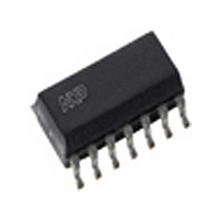
TJA1053T NXP Semiconductors, TJA1053T Datasheet - Page 6

TJA1053T
Manufacturer Part Number
TJA1053T
Description
Manufacturer
NXP Semiconductors
Datasheet
1.TJA1053T.pdf
(20 pages)
Specifications of TJA1053T
Number Of Transceivers
1
Power Down Mode
Sleep/Standby
Operating Supply Voltage (max)
5.25V
Operating Supply Voltage (typ)
5V
Operating Supply Voltage (min)
4.75V
Package Type
SO
Operating Temperature (max)
125C
Operating Temperature (min)
-40C
Operating Temperature Classification
Automotive
Mounting
Surface Mount
Pin Count
14
Lead Free Status / RoHS Status
Compliant
Available stocks
Company
Part Number
Manufacturer
Quantity
Price
Part Number:
TJA1053T
Manufacturer:
PHI
Quantity:
20 000
Company:
Part Number:
TJA1053T/N1
Manufacturer:
NXP
Quantity:
3 522
Part Number:
TJA1053T/N1
Manufacturer:
PHILIPS/飞利浦
Quantity:
20 000
Company:
Part Number:
TJA1053TD
Manufacturer:
PHILIPS
Quantity:
3 268
Company:
Part Number:
TJA1053TN1
Manufacturer:
PH
Quantity:
5 442
Philips Semiconductors
Wake-up requests are recognized by the transceiver when
a dominant signal is detected on either bus line or if the
WAKE pin is connected to ground. On a wake-up request
the transceiver will set the INH output which can be used
to activate the external V
provided the wake-up request can be read on the NERR or
RXD outputs, on which the external microcontroller can
wake up the transceiver (switch to normal operating mode)
via STB and EN.
To prevent false wake-up due to transients or RF fields,
wake-up voltage threshold levels have to be maintained
for a certain period of time. In the low power modes the
failure detection circuit remains partly active to prevent
increased power consumption should errors 3, 4 and 7
occur.
Power on
After power-on V
become HIGH and an internal power-on flag will be set.
This flag can be read via the NERR pin (STB = 1, EN = 0)
and will be reset by entering the normal operation mode.
Table 1 Truth table of CAN transceiver
Notes
1. Wake-up interrupts are released when entering normal operating mode.
2. If go to sleep command was used before (EN may turn LOW as V
3. V
2000 Dec 18
STB EN
0
0
0
1
1
Fault-tolerant CAN transceiver
because of fail safe functionality).
BAT
0
0
1
0
1
power-on flag will be reset when entering normal operation mode.
V
sleep
go to sleep command
V
normal operation mode
BAT
CC
BAT
standby
standby
(2)
is switched on, the INH pin will
MODE
CC
(3)
(1)
voltage regulator. If V
floating
floating
HIGH
HIGH
HIGH
INH
active LOW wake-up interrupt signal if V
active LOW V
power-on flag
active LOW error flag
CC
is
NERR
6
BAT
The EN and STB pins will internally be set to LOW level, if
the V
provide fail safe functionality.
Protections
A current limiting circuit protects the transmitter output
stages against short-circuit to positive and negative
battery voltage.
If the junction temperature exceeds a maximum value, the
transmitter output stages are disabled. Because the
transmitter is responsible for the major part of the power
dissipation, this will result in a reduced power dissipation
and hence a lower chip temperature. All other parts of the
IC will remain operating.
The CANH and CANL inputs are protected against
electrical transients which may occur in an automotive
environment.
CC
voltage is below a certain threshold level, to
CC
drops, without affecting internal functions
active LOW wake-up
interrupt
HIGH = receive;
LOW = dominant
received data
RXD
CC
is present switched to V
Product specification
switched to V
switched to V
switched to V
switched to V
TJA1053
RTL
BAT
BAT
BAT
CC
CC


