5536607-1 TE Connectivity, 5536607-1 Datasheet - Page 51
5536607-1
Manufacturer Part Number
5536607-1
Description
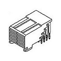
Conn Backplane RCP 8Power POS POS 2mm RA Thru-Hole
Manufacturer
TE Connectivity
Type
Backplaner
Series
Z-PACKr
Specifications of 5536607-1
Pitch
2 mm
Number Of Rows
4
Number Of Contacts
8Power POS
Mounting
Through Hole
Contact Plating
Gold Over Palladium Nickel
Gender
RCP
Body Orientation
Right Angle
Housing Material
Liquid Cryst Polymer
Number Of Ports
1Port
Number Of Terminals
24
Pitch (mm)
2mm
Contact Material
Phosphor Bronze
Voltage Rating Max
30VAC
Mounting Style
Through Hole
Termination Method
Solder
Product Length (mm)
11.88mm
Connector Type
Backplane
Row Pitch
2mm
Pitch Spacing
2mm
No. Of Contacts
8
Contact Termination
Right Angle Through Hole
No. Of Rows
4
Rohs Compliant
Yes
Number Of Positions / Contacts
8
Termination Style
Solder
Product Type
Connector
Pcb Mounting Orientation
Right Angle
Post Type
Solder Post
Module Type
Power
Number Of Power Positions
8
Voltage Rating (vac)
30
Termination Post Length (mm [in])
2.73 [0.107]
Sequencing
No
Post Plating
Tin
Centerline, Matrix (mm [in])
2.00 x 2.00 [.079 x .079]
Contact Type
Socket
Contact Base Material
Phosphor Bronze
Contact Plating, Mating Area, Material
Gold, Gold or Gold Flash over Palladium Nickel
Connector Style
Receptacle
Rohs/elv Compliance
RoHS compliant, ELV compliant
Lead Free Solder Processes
Wave solder capable to 240°C, Wave solder capable to 260°C, Wave solder capable to 265°C, Reflow solder capable to 245°C, Reflow solder capable to 260°C, Pin-in-Paste capable to 245°C, Pin-in-Paste capable to 260°C
Rohs/elv Compliance History
Always was RoHS compliant
Applies To
Printed Circuit Board
Application
Free-Board
Lead Free Status / RoHS Status
Compliant
Lead Free Status / RoHS Status
Compliant


60
Product Facts
■
■
■
■
■
■
■
■
■
Technical Documents
Product Specification
108-2216
Application Specification
114-13156
Industry Standard
PICMG 3.0, Rev. 2.0
AdvancedTCA and PICMG are
trademarks of the PICMG-PCI Industrial
Computer Manufacturers Group, Inc.
Catalog 1773096
Revised 2-10
www.tycoelectronics.com
Designed to PICMG 3.0
Standard
High conductivity copper
alloy on Size 16 power
contacts
.76 micro-meters
[30 microinch] gold over
1.27 micrometers
[50 microinch] nickel
plating at contact interface
Gold-thickness controlled on
inside of socket and outside
of pin — at contact interface
points
RoHS compliant
Stainless steel spring
provides contact normal
force — resists relaxation at
elevated temperatures
Eye of the needle compliant
press-fit termination
No special tools needed to
seat connectors to PCB —
standard Flat-Rock seating
tools
Additional PCB retention
hardware not required
Dimensions are in inches and
millimeters unless otherwise
specified. Values in brackets
are metric equivalents.
Power Connectors & Interconnection Systems
Z1 Power Connector for AdvancedTCA Zone 1 Applications
Introduction
Tyco Electronics supplies
both the power and the
signal connectors
specified in the Advanced
Telecommunications
Computer Architecture
(AdvancedTCA) Standard.
This standard (PICMG 3.0)
is one of the latest stan-
dards addressing future
telecommunications needs.
The AdvancedTCA Power
Connector, designated for
use in Zone 1 per PICMG
3.0, combines 8 High
Conductivity Size 16 pin &
socket contacts along with
22 Size 22 pin & socket
contacts, plus guidance
into a compact interface.
Both connector halves
feature proven compliant
press-fit contacts for easy
solder-less termination to
printed circuit boards.
Based on years of reliable
long-term field installations
the power contact design is
based upon Tyco Electronics’
famous Type III+ contact
design. By adding the use
of a high conductivity cop-
per alloy and the low-force
Eye-Of-Needle compliant
Dimensions are shown for
reference purposes only.
Specifications subject
to change.
pin section, the new con-
tact delivers both ease of
installation (with flat-rock
seating tools) as well as
industry-leading current
carrying capability. The
power contacts are capable
of carrying 20 amps per
contact and the signals are
capable of carrying 2 amps
per contact.
The housing design also
offers improvements com-
pared to other industry
alternatives. The lead-in
design for the contact
cavities provides better
resistance from contact
stubbing. The contact
retention has also been
designed to eliminate the
need for additional hard-
ware sometimes used to
hold the connectors to
the PCB after pressing in to
the PCB.
The result is a connector
which is easy to install,
meets all the PICMG 3.0
performance requirements
and stays retained to the
PCB without the additional
labor required to add
hardware.
USA: 1-800-522-6752
Canada: 1-905-470-4425
Mexico: 01-800-733-8926
C. America: 52-55-1106-0803
Typical Electrical Properties
Current Ratings — tested in
accordance with CSA C22.2 No.
182.3-M1987 and IEC 60512-3, Test 5a
requirements:
Positions 1–24, 27, 32 — 1 Amp each,
per the PICMG 3.0 Specification
Positions 25, 26, 28–31, and 34 —
20 Amps each, exceeds the PICMG 3.0
Specification
Dielectric Withstanding Voltage —
Positions 1–16 — 1000 Volts rms
Positions 17–24 — 2000 Volts rms
Positions 25–34 — 2000 Volts rms
Environmental Parameters
Maximum Continuous Operating
Temperature — 105°C
Durability Rating — 250 cycles, per
PICMG 3.0
South America: 55-11-2103-6000
Hong Kong: 852-2735-1628
Japan: 81-44-844-8013
UK: 44-(0)8002-67666
METRIC
millimeters over inches
Dimensions are
Related parts for 5536607-1
Image
Part Number
Description
Manufacturer
Datasheet
Request
R

Part Number:
Description:
Printers THERMAL PRINTER HS-SLEEVE MARKER
Manufacturer:
TE Connectivity


Part Number:
Description:
High Speed / Modular Connectors 30P HEADER ASSY
Manufacturer:
TE Connectivity
Datasheet:

Part Number:
Description:
High Speed / Modular Connectors REC 6X005P R/A LT B-PLANE HS3
Manufacturer:
TE Connectivity
Datasheet:

Part Number:
Description:
High Speed / Modular Connectors 2MM HM RCPT 50P R/A AU
Manufacturer:
TE Connectivity
Datasheet:

Part Number:
Description:
High Speed / Modular Connectors 2MM HM RCPT 50P R/A AU
Manufacturer:
TE Connectivity
Datasheet:


Part Number:
Description:
Manufacturer:
TE Connectivity
Datasheet:


Part Number:
Description:
Manufacturer:
TE Connectivity
Datasheet:

Part Number:
Description:
Manufacturer:
TE Connectivity
Datasheet:

Part Number:
Description:
Manufacturer:
TE Connectivity
Datasheet: