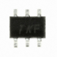
HSMS-286K-BLKG Avago Technologies US Inc., HSMS-286K-BLKG Datasheet - Page 9

HSMS-286K-BLKG
Manufacturer Part Number
HSMS-286K-BLKG
Description
DIODE SCHOTTKY DETECT HF SOT-363
Manufacturer
Avago Technologies US Inc.
Datasheet
1.HSMS-2860-BLKG.pdf
(18 pages)
Specifications of HSMS-286K-BLKG
Diode Type
Schottky - 1 Pair Isolated
Voltage - Peak Reverse (max)
4V
Capacitance @ Vr, F
0.25pF @ 0V, 1MHz
Package / Case
SC-70-6, SC-88, SOT-363
Capacitance Ct
0.25pF
Diode Case Style
SOT-363
Pin Configuration
Unconnected Pair
Breakdown Voltage Min
4V
Forward Voltage
350mV
Mounting Type
Surface Mount
Breakdown Voltage
7V
Capacitance
0.3pF
Current Rating
25A
Rohs Compliant
Yes
Diode Configuration
Dual Independent
Forward Current If Max
1mA
No. Of Pins
6
Lead Free Status / RoHS Status
Lead free / RoHS Compliant
Current - Max
-
Power Dissipation (max)
-
Resistance @ If, F
-
Lead Free Status / RoHS Status
Lead free / RoHS Compliant, Lead free / RoHS Compliant
Other names
516-1938
HSMS-286K-BLKG
HSMS-286K-BLKG
Figure 17. Input Impedance, 3 µA Bias.
The corresponding input match is shown in Figure 18. As
was the case with the lower frequency design, bandwidth
is more than adequate for the intended RFID application.
Figure 18. Input Return Loss, 3 µA Bias.
A word of caution to the designer is in order. A glance
at Figure 17 will reveal the fact that the circuit does
not provide the optimum impedance to the diode at
2.45 GHz. The temptation will be to adjust the circuit
elements to achieve an ideal single frequency match, as
illustrated in Figure 19.
9
Two SMA connectors (E.F. Johnson 142‑0701‑631 or
equivalent), a high‑Q capacitor (ATC 100A101MCA50 or
equivalent), miscellaneous hardware and an HSMS‑286B
are added to create the test circuit shown in Figure 16.
The calculated input impedance for this network is
shown in Figure 17.
-10
-15
-20
-5
0
FREQUENCY (GHz): 2.3-2.6
2.3
HSMS-0005 fig 21 was 18
HSMS-285X fig 22 was 19
FREQUENCY (GHz)
2.45
2.6
Figure 19. Input Impedance. Modified 2.45 GHz Circuit.
This does indeed result in a very good match at midband,
as shown in Figure 20.
Figure 20. Input Return Loss. Modified 2.45 GHz Circuit.
However, bandwidth is narrower and the designer runs
the risk of a shift in the mid band frequency of his circuit
if there is any small deviation in circuit board or diode
character istics due to lot‑to‑lot variation or change in
temper‑ature. The matching technique illustrated in
Figure 17 is much less sensitive to changes in diode and
circuit board processing.
5.8 GHz Detector Circuit
A possible design for a 5.8 GHz detector is given in Figure
21.
Figure 21. 5.8 GHz Matching Network for the HSMS-286x Series at 3 µA Bias.
INPUT
RF
-10
-15
-20
-5
0
FREQUENCY (GHz): 2.3-2.6
2.3
HSMS-0005 fig 23 was 20
2.45 GHz
HSMS-285X fig 24 was 21
TRANSMISSION LINE
DIMENSIONS ARE FOR
MICROSTRIP ON
0.032" THICK FR-4.
WIDTH = 0.045"
LENGTH = 0.073"
WIDTH = 0.016"
LENGTH = 0.037"
FREQUENCY (GHz)
2.45
20 pF
VIDEO
OUT
2.6


