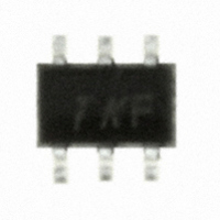
HSMS-286K-BLKG Avago Technologies US Inc., HSMS-286K-BLKG Datasheet - Page 13

HSMS-286K-BLKG
Manufacturer Part Number
HSMS-286K-BLKG
Description
DIODE SCHOTTKY DETECT HF SOT-363
Manufacturer
Avago Technologies US Inc.
Datasheet
1.HSMS-2860-BLKG.pdf
(18 pages)
Specifications of HSMS-286K-BLKG
Diode Type
Schottky - 1 Pair Isolated
Voltage - Peak Reverse (max)
4V
Capacitance @ Vr, F
0.25pF @ 0V, 1MHz
Package / Case
SC-70-6, SC-88, SOT-363
Capacitance Ct
0.25pF
Diode Case Style
SOT-363
Pin Configuration
Unconnected Pair
Breakdown Voltage Min
4V
Forward Voltage
350mV
Mounting Type
Surface Mount
Breakdown Voltage
7V
Capacitance
0.3pF
Current Rating
25A
Rohs Compliant
Yes
Diode Configuration
Dual Independent
Forward Current If Max
1mA
No. Of Pins
6
Lead Free Status / RoHS Status
Lead free / RoHS Compliant
Current - Max
-
Power Dissipation (max)
-
Resistance @ If, F
-
Lead Free Status / RoHS Status
Lead free / RoHS Compliant, Lead free / RoHS Compliant
Other names
516-1938
HSMS-286K-BLKG
HSMS-286K-BLKG
Diode Burnout
Any Schottky junction, be it an RF diode or the gate of
a MESFET, is relatively delicate and can be burned out
with excessive RF power. Many crystal video receivers
used in RFID (tag) applications find themselves in poorly
controlled environments where high power sources may
be present. Examples are the areas around airport and
FAA radars, nearby ham radio operators, the vicinity of
a broadcast band transmitter, etc. In such environments,
the Schottky diodes of the receiver can be protected by
a device known as a limiter diode.
only in radar warning receivers and other high cost
electronic warfare applications, these diodes have been
adapted to commercial and consumer circuits.
Avago offers a com plete line of surface mountable PIN
limiter diodes. Most notably, our HSMP‑4820 (SOT‑23)
or HSMP‑482B (SOT‑323) can act as a very fast (nano‑
second) power‑sensitive switch when placed between
the antenna and the Schottky diode, shorting out the
RF circuit temporarily and reflecting the excessive RF
energy back out the antenna.
[6]
13
Avago Application Note 1050, Low Cost, Surface Mount Power Limiters.
[6]
Formerly available
Assembly Instructions
SOT-323 PCB Footprint
A recommended PCB pad layout for the miniature SOT‑
323 (SC‑70) package is shown in Figure 33 (dimensions
are in inches).
Figure 33. Recommended PCB Pad Layout for Avago’s SC70 3L/SOT-323
Products.
A recommended PCB pad layout for the miniature
SOT‑363 (SC‑70 6 lead) package is shown in Figure 34
(dimensions are in inches). This layout provides ample
allowance for package placement by automated
assembly equipment without adding parasitics that could
impair the performance.
Figure 34. Recommended PCB Pad Layout for Avago’s SC70 6L/SOT-363
Products.
0.035
0.039
0.026
0.026
Dimensions in inches
0.022
0.016
0.079
0.075


