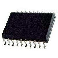
M3004LD STMicroelectronics, M3004LD Datasheet

M3004LD
Specifications of M3004LD
Available stocks
Related parts for M3004LD
M3004LD Summary of contents
Page 1
... The sub-system code may be selected by a press button, a slider switch or hard wired. The M3004LD generates the pattern for driving the output stage. These patterns are pulse distance coded. The pulses are infrared flashes or modulat- ed. The transmission mode is defined in conjunc- tion with the sub-system address ...
Page 2
M3004 Figure 3. Block Diagram INPUTS AND OUTPUTS Key matrix inputs and outputs ...
Page 3
REMOTE CONTROL SIGNAL OUTPUT (REMO) The REMO signal output stage is a push-pull type. In the HIGH state, a bipolar emitter-follower allows a high output current. The timing of the data output format is listed in Table 1 and 2. ...
Page 4
M3004 Table 1. Pulse Train Timing Mode T (ms) O Flashed 2.53 Modulated 2.53 f 455kHz OSC OSC OSC OSC ...
Page 5
Table 3. Transmission Mode and Sub-system Adress Selection Sub-system Address Mode # ...
Page 6
M3004 Table 5. Absolute Maximum Ratings (T Symbol V Supply Voltage Range DD V Input Voltage Range I V Output Voltage Range O ± I D.C. Current into Any Input or Output – I (REMO) M Peak REMO Output Current ...
Page 7
ELECTRICAL CHARACTERISTICS 25°C (unless otherwise specified Table 6. Symbol Parameter V Supply Voltage DD I Supply Current DD f Oscill. Frequency OSC KEYBOARD MATRIX - Inputs SE0N to SEN6N V Input Voltage Low ...
Page 8
M3004 Figure 4. Typical Application Figure 5. Data Format of REMO Output Note: REF = Reference Time; T0 and T1 = Toggle bits; S0, S1 and S2 = System address and F = Command bits. ...
Page 9
Figure 6. REMO Output Waveform Note: (a) flashed pulse (b) modulated pulse [ Figure 7. Single Key - Stroke Sequence Note: Debounce time ...
Page 10
M3004 Figure 8. Multiple Key-Stroke Sequence Note: Scan rate multiple key-stroke : t SM 10/ ...
Page 11
... PART NUMBERING Table 7. Order Codes Order Codes M3004LD M3004LDT Package Operative Temperature Range SO20 SO20 M3004 –20 to +70°C –20 to +70°C 11/14 ...
Page 12
M3004 PACKAGE MECHANICAL Table 8. 20 PINS - PLASTIC MICROPACKAGE Mechanical Data Symbol Min 0. 7 Figure 9. Package Dimensions ...
Page 13
REVISION HISTORY Table 9. Revision History Date Revision November-1992 1 28-June-2004 2 Description of Changes First Issue Stylesheet update. No content change. M3004 13/14 ...
Page 14
... No license is granted by implication or otherwise under any patent or patent rights of STMicroelectronics. Specifications mentioned in this publication are subject to change without notice. This publication supersedes and replaces all information previously supplied. STMicroelectronics products are not authorized for use as critical components in life support devices or systems without express written approval of STMicroelectronics ...


