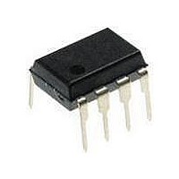
PCF8563PN NXP Semiconductors, PCF8563PN Datasheet - Page 7

PCF8563PN
Manufacturer Part Number
PCF8563PN
Description
Real Time Clock ULTRA LOW POWER CLOCK CALENDAR
Manufacturer
NXP Semiconductors
Datasheet
1.PCF8563TS4118.pdf
(45 pages)
Specifications of PCF8563PN
Function
Clock, Calendar, Alarm, Timer Interrupt
Supply Voltage (max)
5.5 V
Supply Voltage (min)
1.8 V
Maximum Operating Temperature
+ 85 C
Minimum Operating Temperature
- 40 C
Mounting Style
Through Hole
Rtc Bus Interface
Serial
Package / Case
PDIP-8
Time Format
HH:MM:SS
Lead Free Status / RoHS Status
Lead free / RoHS Compliant
Other names
PCF8563P/F4,112
NXP Semiconductors
Table 5.
[1]
[2]
Table 6.
[1]
[2]
PCF8563
Product data sheet
Bit
7
6
5
4
3
2 to 0
Bit
7 to 5
4
3
2
1
0
Default value.
Bits labeled as N should always be written with logic 0.
Bits labeled as N should always be written with logic 0.
Default value.
Symbol
N
TI_TP
AF
TF
AIE
TIE
Symbol
TEST1
N
STOP
N
TESTC
N
Control_status_1 - control and status register 1 (address 00h) bit description
Control_status_2 - control and status register 2 (address 01h) bit description
8.3.1 Register Control_status_1
8.3.2 Register Control_status_2
8.3 Control registers
Value
000
0
1
0
1
0
1
0
1
0
1
Value
0
1
0
0
1
0
0
1
000
[2]
[2]
[2]
[2]
[2]
[1]
[2]
[1]
[2]
[1]
[1]
[2]
Description
normal mode
EXT_CLK test mode
unused
RTC source clock runs
all RTC divider chain flip-flops are asynchronously set to logic 0; the RTC
clock is stopped (CLKOUT at 32.768 kHz is still available)
unused
Power-On Reset (POR) override facility is disabled; set to logic 0 for
normal operation
Power-On Reset (POR) override may be enabled
unused
Description
unused
INT is active when TF is active (subject to the status of TIE)
INT pulses active according to
read: alarm flag inactive
write: alarm flag is cleared
read: alarm flag active
write: alarm flag remains unchanged
read: timer flag inactive
write: timer flag is cleared
read: timer flag active
write: timer flag remains unchanged
alarm interrupt disabled
alarm interrupt enabled
timer interrupt disabled
timer interrupt enabled
must be set to logic 0 during normal operations
Remark: note that if AF and AIE are active then INT will be
permanently active
All information provided in this document is subject to legal disclaimers.
Rev. 8 — 18 November 2010
Table 7
(subject to the status of TIE);
Real-time clock/calendar
PCF8563
© NXP B.V. 2010. All rights reserved.
Reference
Section 8.9
Section 8.10
Section 8.11.1
Reference
Section 8.3.2.1
and
Section 8.8
Section 8.3.2.1
7 of 45


