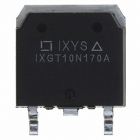
IXGT10N170A IXYS, IXGT10N170A Datasheet
Home Discrete Semiconductor Products IGBTs - Single IXGT10N170A
Manufacturer Part Number
IXGT10N170A
Description
IGBT NPT 1700V 10A TO-268
Specifications of IXGT10N170A
Igbt Type
NPT
Voltage - Collector Emitter Breakdown (max)
1700V
Vce(on) (max) @ Vge, Ic
6V @ 15V, 5A
Current - Collector (ic) (max)
10A
Power - Max
140W
Input Type
Standard
Mounting Type
Surface Mount
Package / Case
TO-268
Channel Type
N
Configuration
Single
Collector-emitter Voltage
1.7kV
Gate To Emitter Voltage (max)
±20V
Package Type
TO-268
Pin Count
2 +Tab
Mounting
Surface Mount
Operating Temperature (min)
-55
Operating Temperature (max)
150C
Operating Temperature Classification
Military
Vces, (v)
1700
Ic25, Tc=25°c, Igbt, (a)
10
Ic90, Tc=90°c, Igbt, (a)
5
Vce(sat), Max, Tj=25°c, Igbt, (v)
6
Tfi, Typ, Igbt, (ns)
190
Eoff, Typ, Tj=125°c, Igbt, (mj)
0.6
Rthjc, Max, Igbt, (°c/w)
1.1
If, Tc=90°c, Diode, (a)
-
Rthjc, Max, Diode, (k/w)
-
Package Style
TO-268
Lead Free Status / RoHS Status
Lead free / RoHS Compliant
Available stocks
High Voltage
IGBT
Symbol
BV
V
I
I
V
Preliminary Data Sheet
Symbol
V
V
V
V
I
I
I
SSOA
(RBSOA)
t
P
T
T
T
M
Maximum lead temperature for soldering
1.6 mm (0.062 in.) from case for 10 s
Weight
© 2003 IXYS All rights reserved
CM
CES
GES
C25
C90
SC
JM
GE(th)
GEM
J
stg
CE(sat)
CES
CGR
GES
C
d
CES
Test Conditions
I
I
V
V
V
I
Test Conditions
T
T
Continuous
Transient
T
T
T
V
Clamped inductive load
T
T
Mounting torque (M3)
C
C
C
GE
J
J
C
C
C
GE
J
C
CE
CE
= 125°C, V
= 25°C to 150°C
= 25°C to 150°C; R
= 25°C
= 90°C
= 25°C, 1 ms
= 15 V, T
= 25°C
= 250 µA, V
= 250 µA, V
= 0.8 • V
= 0 V
= 0 V, V
= I
C90
, V
GE
GE
VJ
CES
CE
= 15 V
= ±20 V
= 125°C, R
GE
CE
= 1200 V; V
= V
= 0 V
GE
GE
Note 1
= 1 MΩ
G
= 22Ω
T
T
GE
(T
J
J
J
= 25°C
= 125°C
= 15 V, R
= 25°C, unless otherwise specified)
T
T
J
J
(TO-247)
= 25°C
= 125°C
TO-247
TO-268
IXGH 10N170A
IXGT 10N170A
G
= 22Ω
1700
min.
3.0
Characteristic Values
-55 ... +150
-55 ... +150
Maximum Ratings
@ 0.8 V
typ.
4.5
5.2
1.13/10Nm/lb.in.
I
CM
1700
1700
300
±20
±30
= 20
10
140
150
10
20
max.
CES
±100
5
6
4
500
5.0
6.0
25
°C
µs
µA
µA
nA
°C
°C
°C
W
V
V
V
V
V
V
V
V
A
A
A
A
g
g
TO-268 (IXGT)
V
I
V
t
TO-247 AD (IXGH)
G = Gate,
E = Emitter,
Features
Applications
Advantages
C25
fi(typ)
International standard packages
JEDEC TO-268 and
JEDEC TO-247 AD
High current handling capability
Very high frequency
MOS Gate turn-on
- drive simplicity
Rugged NPT structure
Molding epoxies meet UL 94 V-0
flammability classification
Pulser circuits
AC motor speed control
DC servo and robot drives
DC choppers
Uninterruptible power supplies (UPS)
Switched-mode and resonant-mode
power supplies
High power density
Suitable for surface mounting
Easy to mount with 1 screw,
(isolated mounting screw hole)
CES
CE(sat)
G
G
C
= 1700
=
=
=
E
C = Collector,
TAB = Collector
E
6.0
DS98991B(11/03)
10
35 ns
C (TAB)
C (TAB)
A
V
V
Related parts for IXGT10N170A
IXGT10N170A Summary of contents
... I = 250 µ GE(th 0.8 • V CES CE CES ± GES CE(sat) C C90 GE © 2003 IXYS All rights reserved IXGH 10N170A IXGT 10N170A Maximum Ratings 1700 = 1 MΩ 1700 GE ±20 ± 22Ω 0 22Ω 140 -55 ... +150 150 -55 ... +150 (TO-247) 1.13/10Nm/lb.in. 300 TO-247 TO-268 ...
... Device must be heatsunk for high temperature leakage current measurements to avoid thermal runaway. Pulse test, t ≤ 300 µs, duty cycle ≤ IXYS reserves the right to change limits, test conditions, and dimensions. IXYS MOSFETs and IGBTs are covered by one or more of the following U.S. patents: Characteristic Values (T = 25° ...
... Fig. 1. Output Characteristics @ 25 Deg Volts CE Fig. 3. Output Characteristics @ 125 Deg Volts CE Fig. 5. Collector-to-Emitter Voltage vs. Gate-to-Emiiter voltage Volts GE © 2003 IXYS All rights reserved 2.6 2 º 7.5 5A 2.5 2. IXGH 10N170A IXGT Fig. 2. Extended Output Characteristics @ 25 deg Volts CE Fig. 4. Temperature Dependence ...
... I - Amperes C Fig. 11. Gate Charge 600V 0mA nanoCoulombs G IXYS reserves the right to change limits, test conditions, and dimensions. IXYS MOSFETs and IGBTs are covered by one or more of the following U.S. patents 0.9 0.8 0.7 0.6 0 off 0.8 0 Ohms G 0.4 0 ...
... IXYS All rights reserved Fig. 13. M axim um T ransient T herm al R esistance 10 Puls e W idth - millis ec onds IXGH 10N170A IXGT 10N170A ...
Related keywords
ixgt16n170 ixgt15n120b ixgt10n170 ixgt10n170a IXGT10N170A datasheet IXGT10N170A data sheet IXGT10N170A pdf datasheet IXGT10N170A component IXGT10N170A part IXGT10N170A distributor IXGT10N170A RoHS IXGT10N170A datasheet download