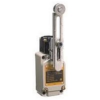
D4BL-K3 Omron, D4BL-K3 Datasheet - Page 14

D4BL-K3
Manufacturer Part Number
D4BL-K3
Description
Contact OSTI For Purchase
Manufacturer
Omron
Type
Safety-Door Switchr
Series
D4BLr
Specifications of D4BL-K3
Contact Form
DPDT
Contact Rating
10 Amps
Actuator
Plunger
Operating Force
19.61 N
Termination Style
Wire
Color
Red
Mounting Style
Screw
Lead Free Status / RoHS Status
Lead free / RoHS Compliant
For Use With
D4BL Guard Lock Safety Door Switches
Lead Free Status / Rohs Status
Lead free / RoHS Compliant
Other names
Q2025725A
Switch and Operation Key Mounting
Mount the D4BL and Operation Key with four M5 screws with
washers and tighten each screw to the specified torque.
Mounting Dimensions
Switch Mounting Dimensions
Operation Key Mounting Holes
Horizontal Mounting
D4BL-K1
Vertical Mounting
D4BL-K2
Adjustable Mounting (Horizontal)
D4BL-K3
74±0.1
20±0.1
40±0.1
30±0.1
100±0.1
Two, M5
Two, M5
Two, M5
Four, M5
15
Head Directions
The head can be mounted in four directions. To remove the head,
turn the head by 45° as shown in figures A and B below.
To change the direction of the head, make sure that the
protruding part of the rotating lever engages with the groove of
the plunger. Then turn the head clockwise or counterclockwise to
the desired direction. At that time, make sure that the groove of
the plunger is located under the rotating lever. If the direction of
the head is not set when the plunger is rotated by 45°, the groove
of the plunger presses the rotating lever. The head, plunger, or
the built-in switch may be damaged as a result.
Head Direction Changes
Front
Head Bottom View
Operation plunger and
groove mechanism
(45°)
Left
(A)
(B)
Switch Top View
Rotation lever and
protruding part
Right
(45°)
Back
D4BL


