TFDU4101-TT3 Vishay, TFDU4101-TT3 Datasheet - Page 7
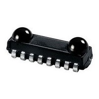
TFDU4101-TT3
Manufacturer Part Number
TFDU4101-TT3
Description
Infrared Transceivers SIR 115.2kbits Top View
Manufacturer
Vishay
Datasheet
1.TFDU4101-TR3.pdf
(13 pages)
Specifications of TFDU4101-TT3
Wavelength
900 nm
Continual Data Transmission
115.2 Kbit/s
Radiant Intensity
65 mW/sr
Half Intensity Angle Degrees
24 deg
Pulse Width
2.2 us
Maximum Rise Time
100 ns, 300 ns
Maximum Fall Time
100 ns, 300 ns
Operating Voltage
2.4 V to 5.5 V
Maximum Operating Temperature
+ 85 C
Minimum Operating Temperature
- 30 C
Dimensions
9.7 mm x 4.7 mm x 4 mm
Data Rate Max
115.2Kbps
Data Transmission Distance
1m
Peak Wavelength
900nm
Supply Current
90µA
Supply Voltage Range
2.4V To 5.5V
Operating Temperature Range
-30°C To +85°C
Msl
MSL 4 - 72 Hours
Data Rate
115.2kbs (SIR)
Idle Current, Typ @ 25° C
75µA
Link Range, Low Power
1m
Operating Temperature
-30°C ~ 85°C
Orientation
Top View
Shutdown
*
Size
9.7mm x 4.7mm x 4mm
Standards
IrPHY 1.0
Supply Voltage
2.4 V ~ 5.5 V
Lead Free Status / RoHS Status
Lead free / RoHS Compliant
Lead Free Status / RoHS Status
Lead free / RoHS Compliant, Lead free / RoHS Compliant
Available stocks
Company
Part Number
Manufacturer
Quantity
Price
Company:

Part Number:
TFDU4101-TT3
Manufacturer:
VISHAY
Quantity:
41 000
Part Number:
TFDU4101-TT3
Manufacturer:
VISHAY/威世
Quantity:
20 000


I/O AND SOFTWARE
In the description, already different I/Os are mentioned.
Different combinations are tested and the function verified
with the special drivers available from the I/O suppliers. In
special cases refer to the I/O manual, the Vishay application
notes, or contact directly Vishay Sales, Marketing or
Application.
Document Number: 81288
Rev. 1.5, 08-Jul-09
TABLE 2 - TRUTH TABLE
V batt
Hi/Low
V s = 2.8 V
20038
> 1 ms
High
≈
Low
SD
3 V
Grey: Optional for high/low Switching.
IR MODE
Fig. 2 - Typical Application Circuit.
V
dd
IRRX
IRTX
High < 50 µs
High > 50 µs
TXD
Low
Low
Low
Infrared Transceiver Module (SIR, 115.2 kbit/s)
x
irdasupportAM@vishay.com, irdasupportAP@vishay.com,
INPUTS
For technical questions within your region, please contact one of the following:
R2
C2
OPTICAL INPUT IRRADIANCE
R1
< max. irradiance E
> max. irradiance E
> min. irradiance E
for IrDA
IRED Anode (1)
IRED Cathode (2)
TXD (3)
RXD (4)
SD (5)
Vcc1 (6)
GND (8)
mW/m
C1
< 4
x
x
x
®
2
Applications
e
e
e
(500 kΩ) to V
Weakly pulled
High inactive
High inactive
Low (active)
Low active
Undefined
CURRENT DERATING DIAGRAM
Figure 3 shows the maximum operating temperature when
the device is operated without external current limiting
resistor.
RXD
18097
90
85
80
75
70
65
60
55
50
OUTPUTS
CC1
2
irdasupportEU@vishay.com
2.5
TRANSMITTER
Operating Voltage (V) at Duty Cycle 20 %
Fig. 3 - Current Derating Diagram
3
I
0
0
0
0
0
Vishays Semiconductors
e
3.5
IrDA defined threshold for noise
4
Response to an IrDA compliant
Overload conditions can cause
Ignoring low signals below the
unexpected outputs
4.5
Protection is active
optical input signal
OPERATION
Transmitting
TFDU4101
REMARK
Shutdown
immunity
5
www.vishay.com
5.5
6
7
Related parts for TFDU4101-TT3
Image
Part Number
Description
Manufacturer
Datasheet
Request
R

Part Number:
Description:
Manufacturer:
Vishay Semiconductors
Datasheet:

Part Number:
Description:
Infrared Transceivers SIR 115.2 kbits/s
Manufacturer:
Vishay
Datasheet:

Part Number:
Description:
357-036-542-201 CARDEDGE 36POS DL .156 BLK LOPRO
Manufacturer:
Vishay
Datasheet:
Part Number:
Description:
357-036-542-201 CARDEDGE 36POS DL .156 BLK LOPRO
Manufacturer:
Vishay
Datasheet:
Part Number:
Description:
357-036-542-201 CARDEDGE 36POS DL .156 BLK LOPRO
Manufacturer:
Vishay
Datasheet:
Part Number:
Description:
357-036-542-201 CARDEDGE 36POS DL .156 BLK LOPRO
Manufacturer:
Vishay
Datasheet:
Part Number:
Description:
357-036-542-201 CARDEDGE 36POS DL .156 BLK LOPRO
Manufacturer:
Vishay
Datasheet:
Part Number:
Description:
357-036-542-201 CARDEDGE 36POS DL .156 BLK LOPRO
Manufacturer:
Vishay
Datasheet:
Part Number:
Description:
357-036-542-201 CARDEDGE 36POS DL .156 BLK LOPRO
Manufacturer:
Vishay
Datasheet:
Part Number:
Description:
357-036-542-201 CARDEDGE 36POS DL .156 BLK LOPRO
Manufacturer:
Vishay
Datasheet:
Part Number:
Description:
357-036-542-201 CARDEDGE 36POS DL .156 BLK LOPRO
Manufacturer:
Vishay
Datasheet:
Part Number:
Description:
357-036-542-201 CARDEDGE 36POS DL .156 BLK LOPRO
Manufacturer:
Vishay
Datasheet:
Part Number:
Description:
357-036-542-201 CARDEDGE 36POS DL .156 BLK LOPRO
Manufacturer:
Vishay
Datasheet:
Part Number:
Description:
357-036-542-201 CARDEDGE 36POS DL .156 BLK LOPRO
Manufacturer:
Vishay
Datasheet:
Part Number:
Description:
357-036-542-201 CARDEDGE 36POS DL .156 BLK LOPRO
Manufacturer:
Vishay
Datasheet: