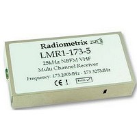
LMR1-173-5 RADIOMETRIX, LMR1-173-5 Datasheet - Page 6

LMR1-173-5
Manufacturer Part Number
LMR1-173-5
Description
RECEIVER, 173.20-173.325MHZ
Manufacturer
RADIOMETRIX
Datasheet
1.LMR1-173-5.pdf
(10 pages)
Specifications of LMR1-173-5
Rohs Compliant
YES
Serial interface commands
2400 baud RS232. 8 bit data, no parity, 1 start bit, 1 or 2 stop bits.
Serial data is sent to the unit on one of the parallel channel select pins (P0). It is very important that the unit
does not 'decode' switch bounce in ordinary operation as a command string, or spurious re-writing of the
e2prom will result. For this reason the user must send the 16 character string ENABLESERIALMODE
(followed by a carriage return) to activate the serial command mode before sending any of the command
strings listed below. Command mode is disabled on power down, or on reception of a # character. To
successfully program the unit, it must be enabled ('RXE high (rx) or TXE low (tx)).
aa = a two digit channel number from 00 to 31
nnnnn = synthesizer N register value (up to 65535)
rrrr = synthesizer R register value (up to 16383)
For LMT1 Transmitter:
For LMR1 Receiver:
Notes: 1. A pause of at least 50ms must be allowed between command strings (EEPROM programming
Radiometrix Ltd
R
N
R
N
GOCHAN aa
LOAD aa
SETPAR
SETSER
RVALUE rrrr
SINGLE nnnnn
<cr>
/
#
TX
RX
f
f
channelspa
channelspa
time).
2. SINGLE mode does not store the N value in EEPROM. Therefore the unit is inoperative after a
power down until either another valid SINGLE command is received, or mode is changed by a
GOCHAN, SETPAR or SETSER command. SINGLE mode is intended for frequency agile
applications.
3. For UK version (173.200 - 173.325MHz band) the following channel assignment is supplied:
f
f
f
Channelspa
f
RF
Xtal
Xtal
f
Channelspa
f
nnnnn
RF
cing
cing
21
cing
4 .
cing
MHz
10
13
25
25
MHz
173
MHz
kHz
kHz
CH0: 173.250MHz
CH1: 173.275MHz
CH2: 173.300MHz
CH3: 173.325MHz
CH4 - CH7: 173.225MHz (only used for alarm applications)
CH8 - CH31: 173.325MHz
25
.
250
173
, So R=400
kHz
, So R=520
Serially select channel aa, where aa is ch0 to ch31
Set value of N register for channel aa, where aa is Channels 0 to 31
Channel selected by 4 bit parallel inputs (ch0 to ch15 only)
Channel selected by most recent GOCHAN operation
Set value for R register
Set value of N for single channel operation.
N value NOT stored in EEPROM
Process entry
Clear all buffers
Disable command mode
MHz
.
250
25
MHz
kHz
6930
21
LMT1/LMR1 Data Sheet
4 .
6074
page 6


