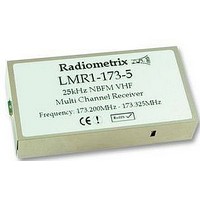
LMR1-173-5 RADIOMETRIX, LMR1-173-5 Datasheet - Page 5

LMR1-173-5
Manufacturer Part Number
LMR1-173-5
Description
RECEIVER, 173.20-173.325MHZ
Manufacturer
RADIOMETRIX
Datasheet
1.LMR1-173-5.pdf
(10 pages)
Specifications of LMR1-173-5
Rohs Compliant
YES
Figure 5: LMR1 footpint (top view)
Pin description – LMR1
NOTES:
Radiometrix Ltd
Pin
1a
2a
3a
4a
5a
1b
2b
3b
4b
5b
1. Serial programming is by an inverted, cmos logic level, 2400 baud RS232 datastream applied to the
2. Channel select inputs have pullups (50k ) to 3v internal rail. Do not exceed 3v logic levels on this
3. Channel select inputs are active low
4. All pins are on an 0.1" grid
5. Data recovery circuit used for RXD is not a simple 'average and compare' type. It is a peak sampling
6. Unit will operate (with marginally reduced specifications) from a 3.0v rail. This must be well regulated
P0 pin.
port.
quasi-DC coupled design, allowing a greater than usual flexibility in data format.
and without noise or ripple, as in this state the unit's internal regulator no longer operates, and
provides no supply rejection.
Name
Vcc
0V
RXE
RXD
AF out
P0/PGM
P1
P2
P3
RSSI
Data out (open collector, no pullup)
Parallel Channel select
Parallel Channel select
Parallel Channel select MSB
Function
3.1 – 15V power supply
Ground
Receiver Enable (active high)
700mV p-p audio. DC coupled, approx 0.8v bias.`
Parallel Channel select LSB
Serial frequency programming / configuration
DC level between 0.5v and 2.2v. 60dB dynamic range
LMT1/LMR1 Data Sheet
1
page 5


