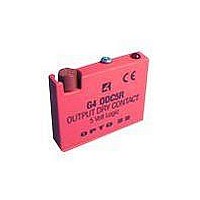
G4ODC5FM OPTO 22, G4ODC5FM Datasheet - Page 25

G4ODC5FM
Manufacturer Part Number
G4ODC5FM
Description
I/O Module
Manufacturer
OPTO 22
Datasheet
1.G4ODC5FM.pdf
(68 pages)
Specifications of G4ODC5FM
Leaded Process Compatible
No
Peak Reflow Compatible (260 C)
No
No. Of Analog Outputs
1
Signal Input Type
4 To 8VDC
Supply Voltage
5V
No. Of Outputs
1
Lead Free Status / RoHS Status
Contains lead / RoHS non-compliant
- Current page: 25 of 68
- Download datasheet (2Mb)
Dimensions—G4PB16I
Connections—G4PB16I
Notes:
1. At each module position on the field terminal
2. Input modules and dry contact output
3. Input modules use even-numbered control
4. To wire output modules for standard
5. To wire output modules for positive-true logic,
See application examples on the following page.
strip, the lower number is always connected to
pin 1 of the module.
modules (G4ODC5R and G4ODC5R5) require
the power supply’s ground to be connected to
the control side’s GND terminal. These modules
also require that odd-numbered connections
on the control side be connected to +VCC.
terminals and can only be wired for
negative-true logic.
negative-true logic, connect the
odd-numbered control terminals to VCC and
use the even-numbered terminals for control.
connect the even-numbered control terminals
to logic ground and use the odd-numbered
terminals for control.
CHAPTER 2: GENERATION 4 DIGITAL I/O MOUNTING RACKS
G4 Digital I/O Family Data Book
Position
Module
10
11
12
13
14
15
0
1
2
3
4
5
6
7
8
9
Connector)
(Header
Control
47
45
43
41
39
37
35
33
31
29
27
25
23
21
19
17
(Terminal Strip)
11 and 12
13 and 14
15 and 16
17 and 18
19 and 20
21 and 22
23 and 24
25 and 26
27 and 28
29 and 30
31 and 32
9 and 10
1 and 2
3 and 4
5 and 6
7 and 8
Field
17
17
Related parts for G4ODC5FM
Image
Part Number
Description
Manufacturer
Datasheet
Request
R

Part Number:
Description:
DC Output Module
Manufacturer:
OPTO 22
Datasheet:

Part Number:
Description:
SSR, PANEL MOUNT, 280VAC, 32VDC, 10A
Manufacturer:
OPTO 22
Datasheet:

Part Number:
Description:
SSR, PANEL MOUNT, 280VAC, 32VDC, 25A
Manufacturer:
OPTO 22
Datasheet:

Part Number:
Description:
SSR, PANEL MOUNT, 280VAC, 32VDC, 25A
Manufacturer:
OPTO 22
Datasheet:

Part Number:
Description:
SSR, PANEL MOUNT, 280VAC, 32VDC, 45A
Manufacturer:
OPTO 22
Datasheet:

Part Number:
Description:
SSR, PANEL MOUNT, 280VAC, 32VDC, 45A
Manufacturer:
OPTO 22
Datasheet:

Part Number:
Description:
SSR, 10A, 240VAC
Manufacturer:
OPTO 22
Datasheet:

Part Number:
Description:
Programmable Logic Controller
Manufacturer:
OPTO 22
Datasheet:

Part Number:
Description:
Programmable Logic Controller
Manufacturer:
OPTO 22
Datasheet:

Part Number:
Description:
Solid State Relays, Accessories
Manufacturer:
OPTO 22
Datasheet:


